Transverse electric field liquid crystal display
A liquid crystal display, transverse electric field technology, applied in the directions of instruments, circuits, transistors, etc., can solve the problems of uneven friction of the calibration layer 113 and uneven display of the liquid crystal display, etc., to reduce uneven friction, improve smoothness, and uniform friction. Effect
- Summary
- Abstract
- Description
- Claims
- Application Information
AI Technical Summary
Problems solved by technology
Method used
Image

Examples
Embodiment Construction
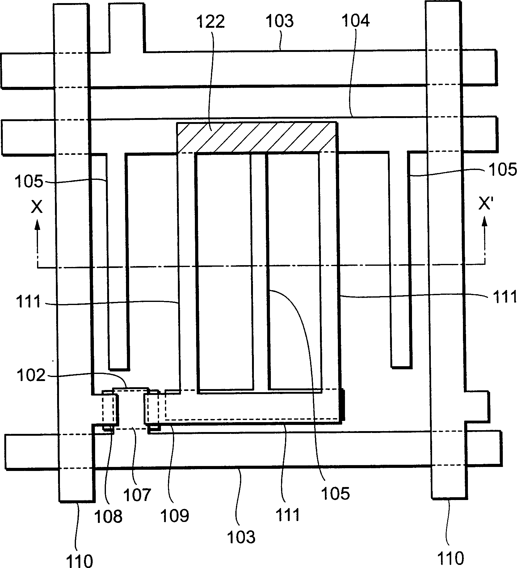
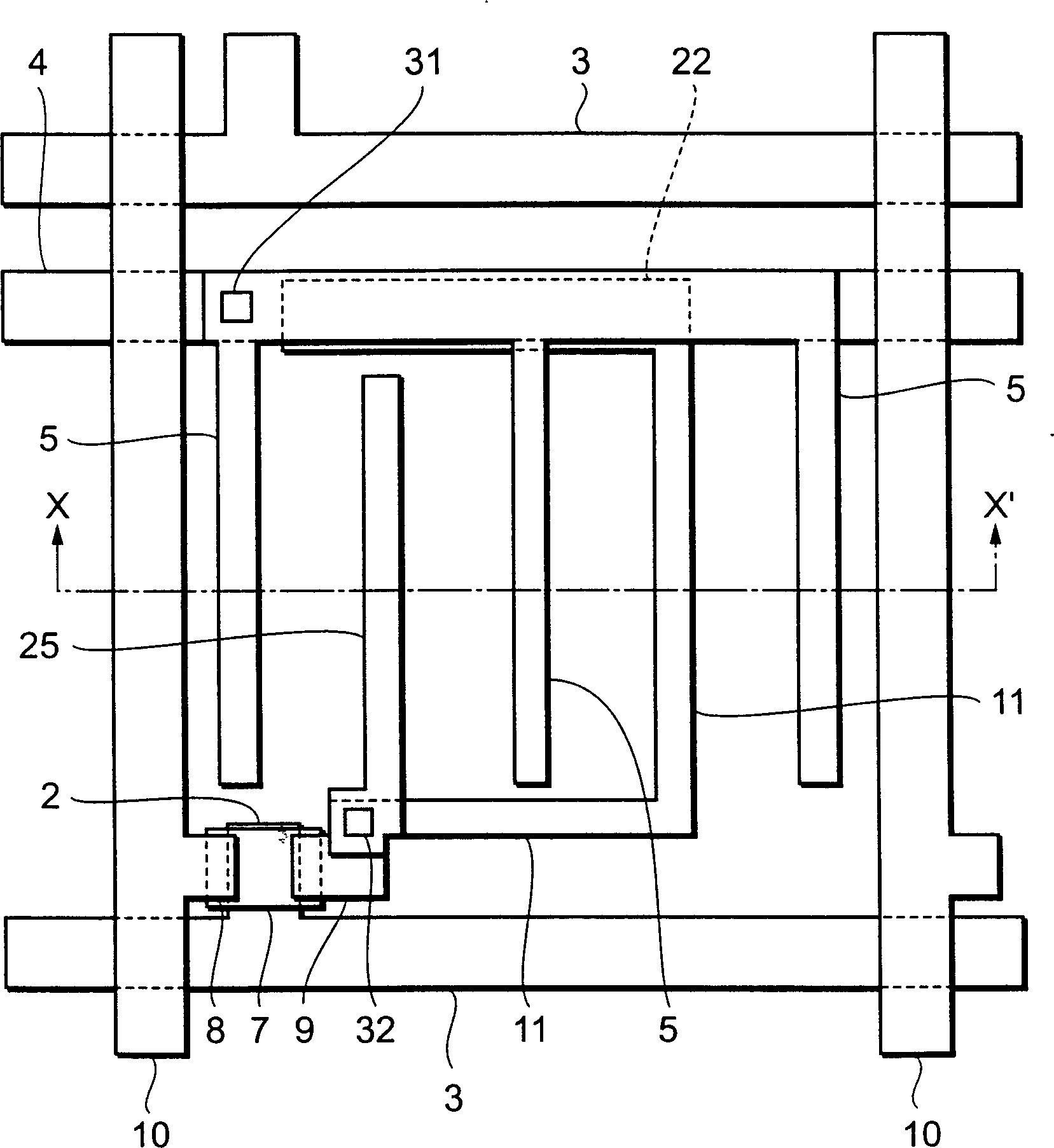
[0020] Hereinafter, examples of liquid crystal displays according to the present invention will be based on image 3 and Figure 4 is described.
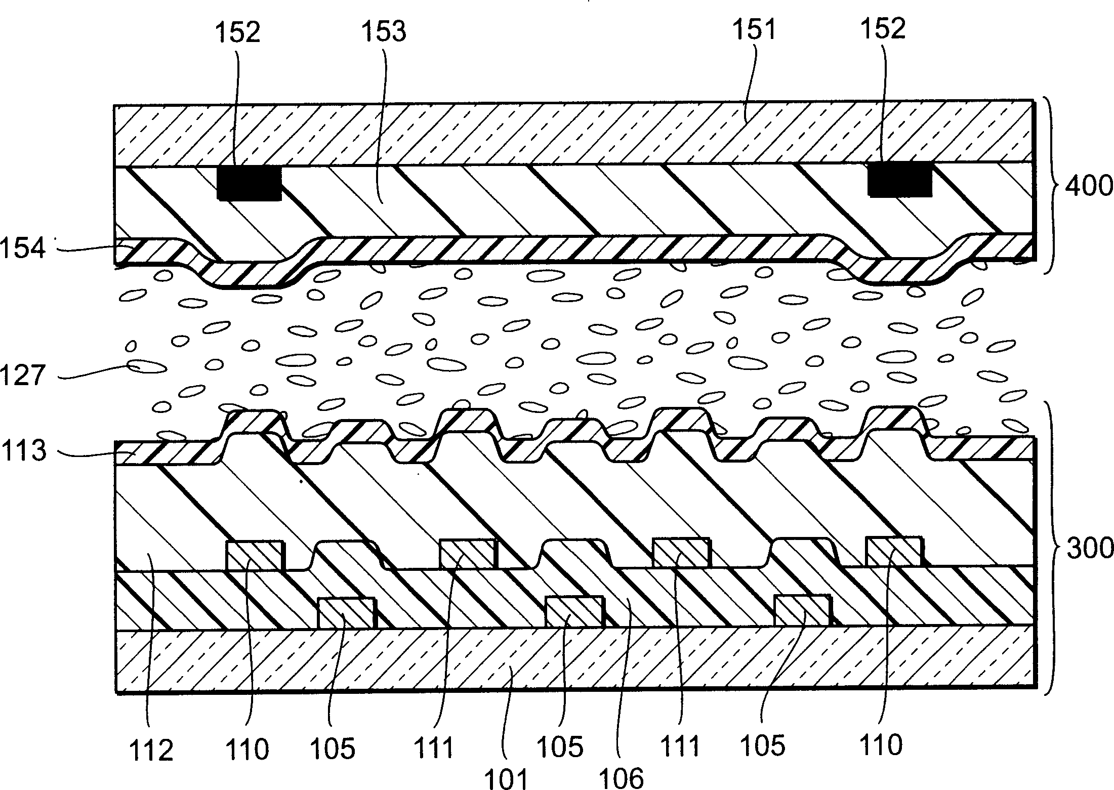
[0021] In order to simultaneously form the scanning line 3, the gate electrode 2 connected to the scanning line 3, and the common line 4, a thickness of 200 to 500 nanometers (chromium (Cr), aluminum (Al), or tantalum (Ta), or an alloy of the above metals) A metal film is patterned on a transparent insulating substrate 1 formed of glass, for example. Thereafter, a gate insulating film 6 such as a silicon nitride (SiNx) film having a thickness of 400 to 600 nm is formed over the substrate. Then, a semiconductor island 7 (for example, amorphous silicon or polysilicon) is formed over the gate insulating film 6 . Thereafter, a metal film (chromium, aluminum, or tantalum, or an alloy of the above metals) having a thickness of 200 to 500 nanometers is deposited and patterned to form signal lines 10, source / drain electrodes 8, 9, and co...
PUM
 Abstract
Description
Claims
Application Information
 - R&D
- Intellectual Property
- Life Sciences
- Materials
- Tech Scout
- Unparalleled Data Quality
- Higher Quality Content
- 60% Fewer Hallucinations
Browse by: Latest US Patents, China's latest patents, Technical Efficacy Thesaurus, Application Domain, Technology Topic, Popular Technical Reports.
© 2025 PatSnap. All rights reserved.Legal|Privacy policy|Modern Slavery Act Transparency Statement|Sitemap|About US| Contact US: help@patsnap.com