Biological electric wound therapeutical devices

A technology of bioelectricity and therapeutic equipment, applied in treatment, electrotherapy, etc., can solve the problems of susceptibility to infection, long treatment time, high cost, etc., and achieve the effect of changing the permeability of blood vessels

Inactive Publication Date: 2003-09-03
方墨希 +1
View PDF0 Cites 4 Cited by
  • Summary
  • Abstract
  • Description
  • Claims
  • Application Information

AI Technical Summary

Problems solved by technology

[0003] Now the treatment of wounds, including scalds, burns, and wounds on the battlefield, is to apply medicine or other methods...

Method used


Image

  • Biological electric wound therapeutical devices
  • Biological electric wound therapeutical devices
  • Biological electric wound therapeutical devices

Examples


Embodiment Construction

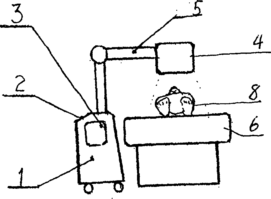
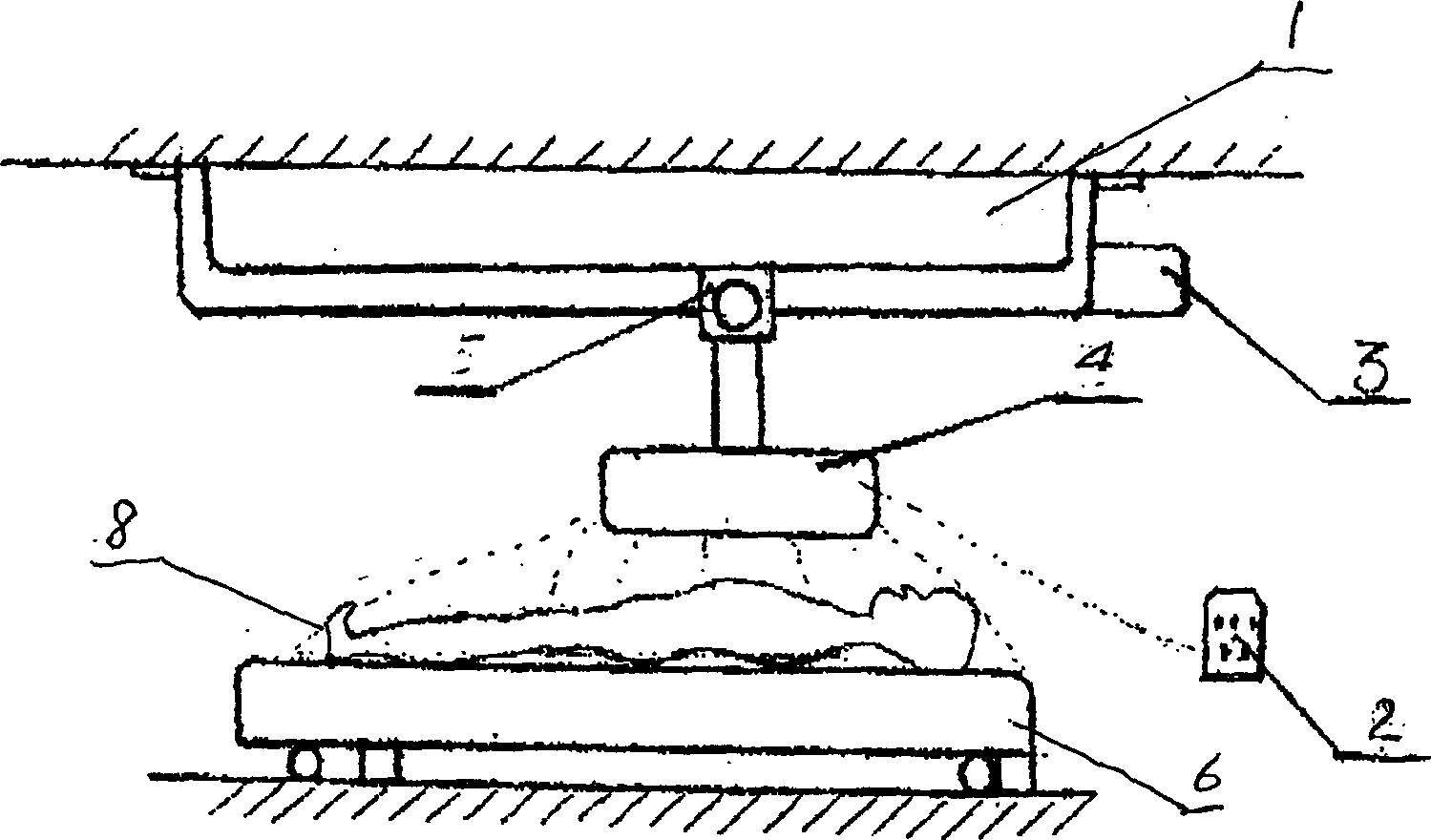
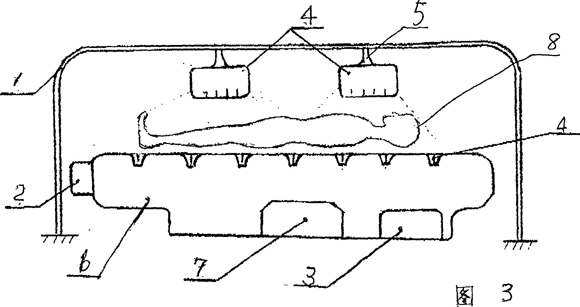
[0018] Such as figure 1 Shown is a universal bioelectric wound therapy instrument. It is composed of a movable support 1, a control device 2, a power source 3, a bioelectric generating device 4, a telescopic mobile support arm 5 and a treatment bed 6.

[0019] The movable stent 1 makes the treatment device reach the use position, powered by the power supply 3. Through the control device 2, the up, down, left, right and rotation of the telescopic support arm 5 can be controlled according to the needs of the wounded 8 to control and adjust the bioelectricity generation The location of the device to treat the injured 8. The feature of this device is that the injured person must be covered in an area full of bioelectricity, and there should be enough space to meet this requirement. The bioelectric density formed by negatively charged nanoparticles in this area should reach 10 5个 -10 9个 / cm 3 , Thereby changing the living environment of bacteria and viruses, and achieve the purpose ...


PUM


Abstract

A bioelectric therapeutic apparatus for wound is composed of a controller with negatively charged nano particles generator, power supply, bioelectric generator, telescopic supporting arm with therapeutic probes, and supporting frame or bed. It has high biologic effect to human physiological state, tissue cells and metabolism and make the wound in aseptic region, resulting in fast heatling.

Description

Technical field: [0001] The invention relates to a wound treatment instrument, in particular to a treatment instrument that uses a device and method for generating negatively charged nanoparticles to treat wounds. The size of negatively charged nanoparticles is smaller than red blood cells and common bacteria in the blood, and is a fraction of them or smaller. They can enter the body through human respiration and skin and mucous membranes, reach the lungs and enter the blood circulation, and release their charge. It then improves the state of cell wall charge and becomes bioelectricity that can produce direct biological effects on the physiological state of the human body, tissue cells and metabolic processes. The device for generating negatively charged nanoparticles has been patented in July 2001. [0002] Since negatively charged nanoparticles have obvious biological effects on the human body and their effects on the human body and the surrounding environment, the bioelectricit...

Claims


Application Information

Patent Timeline
IPC IPC(8): A61N1/00
Inventor 方墨希孙岳
Owner 方墨希
Why Eureka
Try Eureka