Hydraulic lift energy-saving control system with hydraulic transformer

An energy-saving control system and hydraulic transformer technology, applied in elevators, transportation and packaging, etc., can solve the problems of high system cost and large installed power, and achieve real-time control, reuse, and fast dynamic response.

Inactive Publication Date: 2003-09-03
ZHEJIANG UNIV
View PDF0 Cites 35 Cited by
  • Summary
  • Abstract
  • Description
  • Claims
  • Application Information

AI Technical Summary

Problems solved by technology

Compared with the traditional valve-controlled speed control system, this system has the advantages of load power adaptation and partial recovery of downlink energy, so it is much more energy-efficient than the valve-controlled system, but the installed power is still relatively large, and the system is expensive due to the use of frequency converters

Method used


Image

  • Hydraulic lift energy-saving control system with hydraulic transformer
  • Hydraulic lift energy-saving control system with hydraulic transformer

Examples


Embodiment Construction

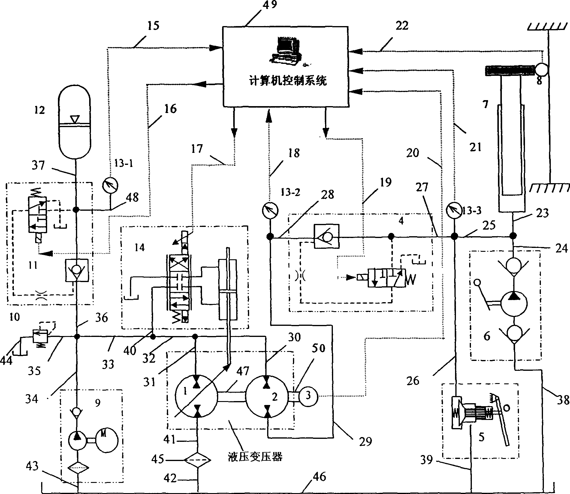
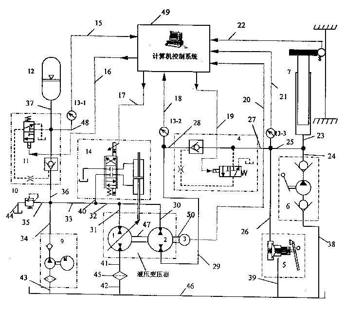
[0012] The accompanying drawing is a structural schematic diagram of a hydraulic elevator energy-saving control system using a hydraulic transformer, wherein: 1 is a variable pump / motor, one end is connected to a filter 45 through a pipeline 41, and an oil tank 46 is connected through a pipeline 42, and one end is connected through a pipeline 31 and The pipelines 32 and 30 are connected, and are coaxially connected with the quantitative pump / motor 2 through a coupling 47. The 2 is a quantitative pump / motor, one end is connected with the pipelines 31 and 32 through the pipeline 30, and the other end is connected with the pipeline 29 through the pipeline 29. The pressure sensor 13-2 is connected, 3 is the speed measuring photoelectric encoder, which is installed on the other shaft end of the quantitative pump / motor 2 through another coupling (50), 4 is the hydraulic control check valve of the main circuit, and one end passes through the pipeline 28 is connected with the pressure ...


PUM


Abstract

An energy-saving control system for hydraulic elevator features use of a hydraulic pressure changer composed of variable or quantitative pump and motor. Said pressure changer can get energy from constant-pressure network and provide it to load without pressure loss, or reverse the energy from load. Its avdantages are high dynamic response speed and pressure amplifying effect.

Description

technical field [0001] The invention relates to a hydraulic elevator energy-saving control system using a hydraulic transformer. Background technique [0002] From the beginning of its production, the hydraulic elevator has experienced the development process from the valve-controlled hydraulic system to the frequency conversion control hydraulic system, and energy saving and consumption reduction has always been one of the major topics of research and development in this field. [0003] The traditional valve-controlled throttling speed regulation system is the most mature technology and the most widely used in the current hydraulic elevator control system. It mainly uses the throttling speed regulation technology in hydraulic technology to control the running speed of hydraulic elevators. Its biggest advantage is that the system is simple, the control is convenient, and the price is low. However, since the throttle is used for speed regulation, a large...

Claims


Application Information

Patent Timeline
Patent Type & Authority Applications(China)
IPC IPC(8): B66B1/04
Inventor 徐兵杨华勇欧阳小平刘贺
Owner ZHEJIANG UNIV
Why Eureka
Try Eureka