A pump-controlled semi-active heave compensation system and its working method

A heave compensation and semi-active technology, applied in the direction of fluid pressure actuation system components, fluid pressure actuation devices, servo motors, etc., can solve the problem of small hydraulic cylinder compensation range, large winch diameter, active compensation complex and large energy consumption, etc. problems, to achieve the effect of stable work and reduced equipped power

Active Publication Date: 2020-04-21
SHANDONG UNIV
View PDF8 Cites 1 Cited by
  • Summary
  • Abstract
  • Description
  • Claims
  • Application Information

AI Technical Summary

Problems solved by technology

The valve-controlled hydraulic cylinder compensation system is characterized by fast response and large tonnage. However, since the valve-controlled hydraulic cylinder compensation system uses proportional valve throttling control to control the expansion and contraction speed and position of the hydraulic cylinder, the pressure drop at the orifice is all Heat is generated to heat up the oil, which makes the efficiency of the valve control system relatively low; the technology of the secondary motor control compensation system is relatively mature, but when dealing with large-tonnage, high-power and long-period operations, the diameter of the winch will be large, which cannot meet the space requirements
[0006] To sum up, most of the current hydraulic cylinder compensation devices have the characteristics of low passive compensation compensation accuracy, active compensation complex energy consumption, small hydraulic cylinder compensation range, etc., and the disadvantage of the existing systems is that they require advanced proportional servo valve control Driven by powerful hydraulic power, the overall comprehensive performance needs to be further optimized and upgraded

Method used


Image

  • A pump-controlled semi-active heave compensation system and its working method
  • A pump-controlled semi-active heave compensation system and its working method
  • A pump-controlled semi-active heave compensation system and its working method

Examples


Embodiment 1

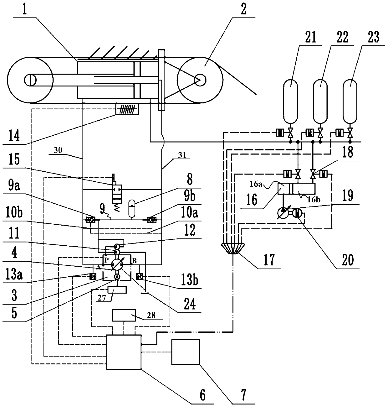
[0058] Such as Figure 1-5 As shown, a pump-controlled semi-active heave compensation system includes a composite hydraulic cylinder 1, a hydraulic power unit 3 and a control unit, wherein:

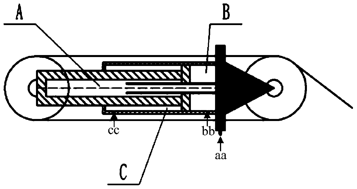
[0059]The composite hydraulic cylinder 1 is a three-chamber combined hydraulic cylinder. The composite hydraulic cylinder 1 is composed of a double-acting piston hydraulic cylinder and a single-acting plunger hydraulic cylinder. The rodless chamber A chamber and the air chamber B chamber, the rod chamber C chamber and the rodless chamber A chamber are isolated from each other by the piston, and the C chamber is connected to the first oil circuit through the cc port for oil suction and return movement; B The cavity is the air cavity connected to the regulating gas cylinder and the working gas cylinder through the bb port to achieve passive compensation. The A cavity is connected to the second oil circuit through the aa port to perform oil suction and return movements. The composite hydraul...

Embodiment 2

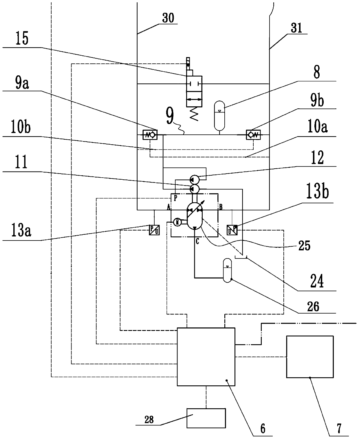
[0068] A pump-controlled semi-active heave compensation system, including a composite hydraulic cylinder 1, a hydraulic transformer 25 and a control unit, where the hydraulic transformer 25 is used in Embodiment 1 to replace the above-mentioned hydraulic power unit 3, wherein:

[0069] One way of the hydraulic transformer 25 is connected to the rod cavity C of the composite hydraulic cylinder 1 through the A port via the first oil passage 30, and the other is connected to the rodless chamber A of the composite hydraulic cylinder 1 through the B port via the second oil passage 31 cavity, the third road is connected with a low-pressure pump 11, the low-pressure pump 11 is connected with an oil tank 24, and the hydraulic transformer 25 is also connected with a hydraulic accumulator 26;

[0070] This hydraulic transformer 25 can be used as both a pump and a motor, allowing energy to be recovered and stored. By connecting the hydraulic transformer 25 in series with the hydraulic ac...

Embodiment 3

[0074] A pump-controlled semi-active heave compensation system, the structure of which is shown in Embodiment 1. The difference is that the working gas cylinders include 22 high-pressure working gas cylinders and 23 low-pressure working gas cylinders, 21 regulating gas cylinders, and 21 high-pressure working gas cylinders. 22 and the low-pressure working gas cylinder 23 are provided with on-off valves, and the on-off valves are connected to the second motor 29, and each second motor 29 is connected to the compensation controller 6 through the harness 17.


PUM


Abstract

The invention relates to a pump control type semi-driving heave compensation system and a working method thereof and belongs to the field of deep sea exploration and operation. The system comprises acomposite hydraulic cylinder, a hydraulic power unit and a control unit. A three-cavity combined type hydraulic cylinder is adopted as the composite hydraulic cylinder. The composite hydraulic cylinder comprises a cavity C, a cavity A and a gas cavity B. The hydraulic powder unit comprises a bidirectional variable pump and a motor. One way of the bidirectional variable pump communicates with the cavity C through a first oil way by means of an oil opening A, another way communicates with the cavity A through a second oil way by means of an oil opening B, and the third way is connected with a low-pressure pump. The control unit comprises a compensation controller, a first pressure sensor, a second pressure sensor, a displacement sensor and a rotating speed sensor, wherein the first pressuresensor, the second pressure sensor, the displacement sensor and the rotating speed sensor are connected with the compensation controller. The bidirectional variable pump is also connected with the compensation controller which is further connected with a motion reference unit. The cavity B is connected with an adjusting gas bottle and a working gas bottle. According to the system, the system is designed by utilizing the high-pressure regeneration property of energy in the wave compensation process, and the compensation range is enlarged.

Description

technical field [0001] The invention relates to a pump-controlled semi-active heave compensation system and a working method thereof, belonging to the technical field of deep-sea detection and operation. Background technique [0002] With the continuous development of marine resources, people's attention and research on the ocean are deepening, and the engineering infrastructure in the field of deep-sea exploration is the basis for marine operations. However, during the installation process of the subsea production facilities in deep water, the position in the water needs to be kept unchanged, but because the mother ship is affected by the fluctuation of the sea surface, the mother ship will move up and down, which seriously interferes with the centering and installation of the subsea equipment. To be independent of effects due to waves, tides, etc., heave compensation systems are usually indispensable in deep water installations. [0003] Hydraulic transmission has been wi...

Claims


Application Information

Patent Timeline
Patent Type & Authority Patents(China)
IPC IPC(8): F15B11/17F15B21/041F15B21/0423F15B15/14
CPCF15B11/17F15B15/1423F15B15/1428F15B15/1457F15B21/04
Inventor 李世振刘延俊龚良奎颜飞
Owner SHANDONG UNIV
Why Eureka
Try Eureka