Improved photoelectric module assembly parts

A technology of photoelectric modules and components, applied in optical components, electrical components, optics, etc., can solve the problems of occupation, inability to provide shielding electromagnetic interference, and multiple PCB spaces, so as to improve the overall capacity, enhance EMI shielding ability, and save PCB space Effect

Inactive Publication Date: 2003-09-17
BROADCOM INT PTE LTD
View PDF0 Cites 3 Cited by
  • Summary
  • Abstract
  • Description
  • Claims
  • Application Information

AI Technical Summary

Problems solved by technology

[0005] Fixing the optical module directly on the board requires too much PCB space, and the figure 1 The chassis assembly shown is such that the module can only be inserted through the front of the board
[0006] Moreover, the above-mentioned mounting methods alone do not provide sufficient shielding against electromagnetic interference (EMI)
EMI shielding function needs to be obtained by additional independent shielding device, thus occupying more PCB space

Method used


Image

  • Improved photoelectric module assembly parts
  • Improved photoelectric module assembly parts
  • Improved photoelectric module assembly parts

Examples


Embodiment Construction

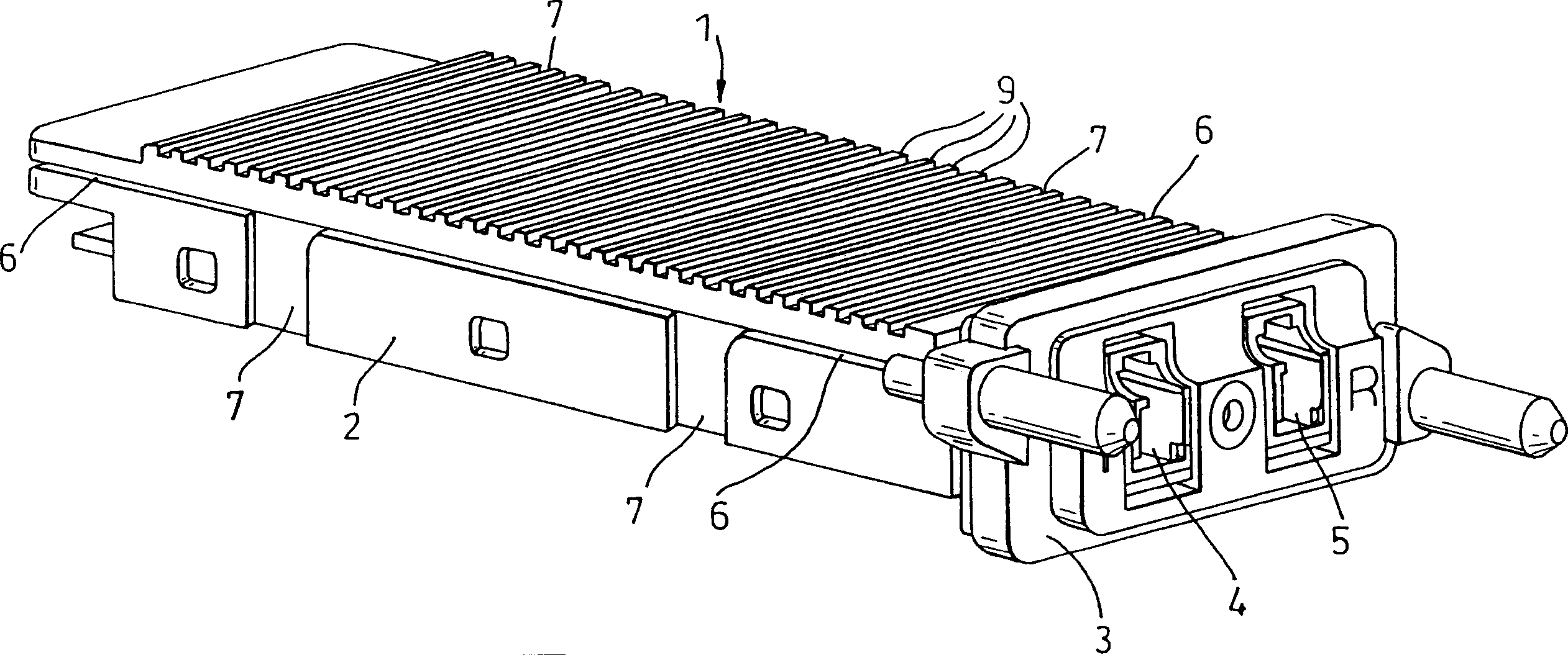
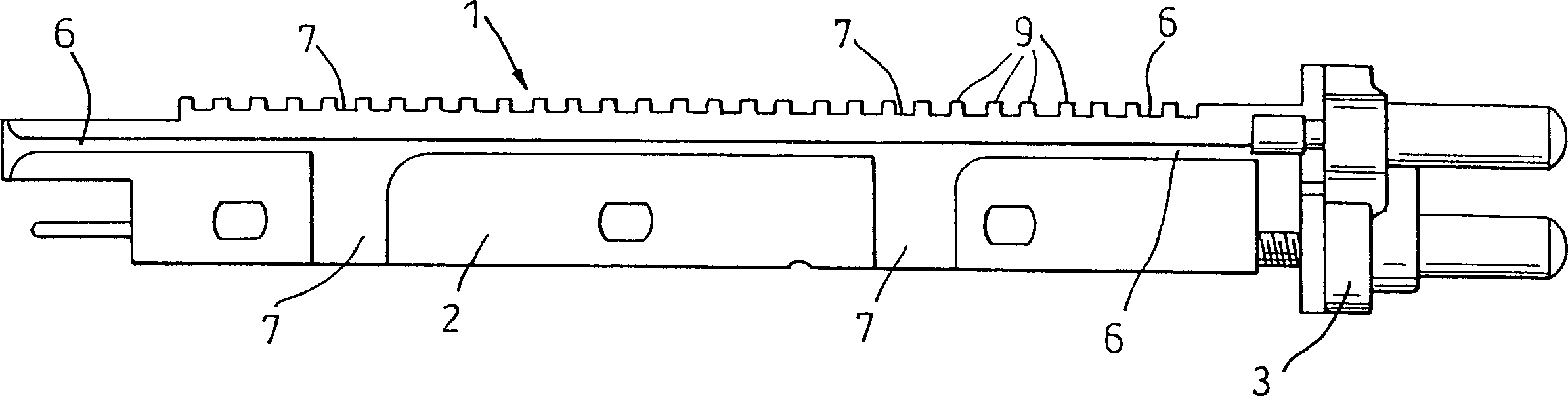
[0031] Such as Figure 2a versus 2b As shown, according to the present invention, the optoelectronic module 1 includes a housing 2, a front cover 3, and channels 4 and 5. The housing and the front cover are preferably made of metal materials. However, other suitable materials such as moderately filled and coated polymers can also be used. The casing is provided with a series of fins 9 arranged in rows to serve as heat sinks. Channels 4 and 5 provide access to the internal components of the module. In this embodiment, the channel 4 provides a way to connect to an optical signal transmitter (not shown in the figure) and the channel 5 provides a way to connect to an optical signal receiver (not shown in the figure). Alternatively, the channel 4 can provide a way to connect to the receiver and the channel 5 can provide a way to connect to the transmitter.

[0032] in Figure 2a versus 2b In the preferred embodiment shown, the holes 4 and 5 are of a type suitable for receiving optical ...


PUM


Abstract

The invention involves a photoelectric module component that can be inserted into the DWDM system and can be disassembled from the system.This component includes a photoelectric module (1) with multiple horizontal grooves (6) and multiple vertical slots (7). The groove and slot enable this optoelectronics module to insertLocated on multiple protrusions on the module installation device.The invention also integrates the EMI shielding function inside the component.

Description

Technical field [0001] The invention relates to an improved photoelectric module assembly applied to a communication or network system. Specifically, the present invention relates to an improved fiber optic module that can be inserted into and removed from a communication / network system. Background technique [0002] As the capacity of the communication / network system increases, there is an increasing demand for optical modules that can be inserted into or unloaded from the system without powering off the system. This mode of operation is called "hot plugging" in the art. [0003] Moreover, the communication / network system also has a trend towards higher integration. This means that users want to be able to add more components and / or modules to the system in the smallest possible space. Therefore, it is necessary to provide the components and modules that can be installed on the user board with the least board space to obtain the maximum density of user board modules. And using l...

Claims


Application Information

Patent Timeline
Patent Type & Authority Applications(China)
IPC IPC(8): G02B6/42
CPCG02B6/4201G02B6/4277G02B6/4261
Inventor 丹尼尔·基布尔克里斯托弗·约翰·奥德贡萨洛·阿格拉·阿莫里姆
Owner BROADCOM INT PTE LTD
Why Eureka
Try Eureka