Positive encapsulating management tool with pair of optical collimators and encapsulation method using the tool

A packaging method and collimator technology, applied in the coupling of optical waveguides, etc., can solve the problems of failure to provide operator adjustment functions, loss of accuracy, and incorrect accuracy

Inactive Publication Date: 2003-10-08
ASIA OPTICAL CO INC
View PDF1 Cites 5 Cited by
  • Summary
  • Abstract
  • Description
  • Claims
  • Application Information

AI Technical Summary

Problems solved by technology

[0004] One, the accuracy is not easy to maintain: the aforementioned prior art is to hold the operating rod 913 by hand during adjustment, so as to adjust the angle and position of the optical fiber guide 91 in the glass tube 90, but, in the process of colloid curing (such as Thermosetting glue needs to be heated and cured, UV glue needs to be cured by ultraviolet radiation), the user's hand must maintain its position and angle and cannot let go of the operating rod 913, and the best position of the optical fiber guide 91 is easily lost due to the vibration of the human hand In addition, since the optical fiber 912 has been twisted to generate stress during adjustment, if the hand is released, the optical fiber 912 will rotate in the opposite direction to achieve a balance of stress, and the optical fiber guide 91 will therefore rotate, causing the angle to be incorrect
[0005] 2. The fine-tuning effect of the jig is not good: the aforementioned jig 95 is only used for fixing, and does not provide a more convenient adjustment function for the operator. The operator can still handle it with bare hands when adjusting, and cannot perform more subtle The adjustment can only achieve an approximate state
[0006] 3. Low yield rate and slow production speed: Before the colloid curing operation, the optical fiber is easy to drive the capillary to rotate due to the aforementioned stress, resulting in incorrect accuracy. Therefore, before the colloid is solidified, the accuracy must be checked again. If the accuracy is lost, the operator has to take it back and readjust, which not only lowers the yield rate, but also slows down the production speed

Method used


Image

  • Positive encapsulating management tool with pair of optical collimators and encapsulation method using the tool
  • Positive encapsulating management tool with pair of optical collimators and encapsulation method using the tool
  • Positive encapsulating management tool with pair of optical collimators and encapsulation method using the tool

Examples


Embodiment Construction

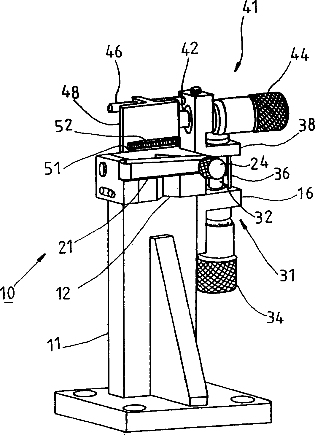
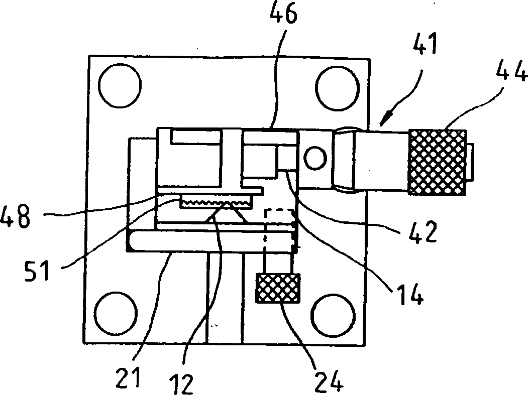
[0038] see Figure 2 to Figure 4 , an optical collimator alignment package jig 10 provided by a preferred embodiment of the present invention is mainly composed of a frame body 11, a clamping member 21, a Z-axis moving platform 31, and an X-axis moving platform 41 , and a set of moving parts 51, wherein:

[0039] The frame body 11 has a groove 12 at a predetermined position. One side is provided with a fixed table 16;

[0040] The clamping member 21 is a rod body, one end is set on the frame body 11 and can be opened and closed corresponding to the groove 12, and the other end is pierced with a bolt 24, when the rod body is attached to the frame body 11 , the bolt 24 can be screwed into the screw hole 14, so as to fix the clamped object;

[0041] The Z-axis moving platform 31 is composed of a screw rod 32, a knob 34 sleeved at the control end of the screw rod 32, a certain guide rod 36, and a connecting platform 38 arranged at the free end of the screw rod 32; the screw rod...


PUM


Abstract

This invention relates to an optical collimator head-on package device and a method in which, the device includes: a frame, a clamper, a z axle moving platform, an x axle moving plalaform and a gear row in which, a fiber tube sleeved by a glass bushing is held by the device them a graded optical signal Grin-lens end is rested with a gear and sleeved by a glass bushing. The gear connection relationship of the gear and gear row is used to make the Grin-lens shift up and down or rotate through x, z axle shifting platforms to adjust location and angle of the Grain-lens related to strong or weak light signals to keep it unchanged to ensure the head-on location when fixing the lens and glass bushing with glue.

Description

technical field [0001] The present invention is related to optical devices, and more specifically, refers to an optical collimator (collimator) alignment packaging jig and a packaging method using the jig. Background technique [0002] Press, known jig and method for manufacturing optical collimator, such as figure 1 As shown in the U.S. Patent No. 6,168,319, an optical fiber guide 91 and a gradient optical signal glass column (Grin-lens) 92 are sleeved inside a glass tube 90, and a jig 95 is used to clamp it horizontally Hold, and wherein between the capillary 911 of the optical fiber conduit 91 and the glass tube 90 is provided with colloid, and the colloid has not yet solidified, the end of the optical fiber 912 at the outer end of the optical fiber conduit 91 is connected to a laser signal transmitter 93, the root of the optical fiber 912 The position is connected with an operating rod 913, which can be held and operated by hand, so as to control the position and angle ...

Claims


Application Information

Patent Timeline
Patent Type & Authority Applications(China)
IPC IPC(8): G02B6/24G02B6/38
Inventor 赵圣瑞林志贤刘元凯
Owner ASIA OPTICAL CO INC
Why Eureka
Try Eureka