Supercharge Your Innovation With Domain-Expert AI Agents!

Deflecting coil

A technology of deflection coils and coils, which is applied in the direction of cathode ray tube indicators, cathode ray tubes/electron beam tubes, instruments, etc., which can solve the problem of reducing work and production efficiency, easily damaging both sides of the upper end, and printed circuit boards cannot be supported Power and other issues

Inactive Publication Date: 2003-10-29
SAMSUNG ELECTRO MECHANICS CO LTD
View PDF0 Cites 0 Cited by
  • Summary
  • Abstract
  • Description
  • Claims
  • Application Information

AI Technical Summary

Problems solved by technology

[0015] However, from the perspective of the conventional deflection yoke, the printed circuit board (200) has the following characteristics when assembled to the rear cover (11b). image 3 As shown, due to the operator's assembly force, it is easy to damage the disadvantages of both sides of the upper end
This is because a pair of upper hook sheet (310) and lower hook sheet (320) that provide the supporting force of the printed circuit board (200) are installed in the diameter of the pipe neck (12) that is arranged on the coil separator (10), so the above-mentioned While the central part of the printed circuit board (200) of the upper hook piece (310) and the lower hook piece (320) will receive a strong supporting force, on the contrary, the two sides of the upper end of the printed circuit board (200) cannot be supported. force, resulting in cracks and breakage
[0016] Accordingly, the operator should pay special attention to prevent damage to both sides of the upper end of the printed circuit board (200) during assembly, so the work and production efficiency will be reduced.

Method used


Image

  • Deflecting coil
  • Deflecting coil
  • Deflecting coil

Examples


Embodiment Construction

[0034] By following the detailed description of the invention with reference to the accompanying drawings, the present invention will be better understood, and the various objects and various advantages of the present invention will be more fully appreciated.

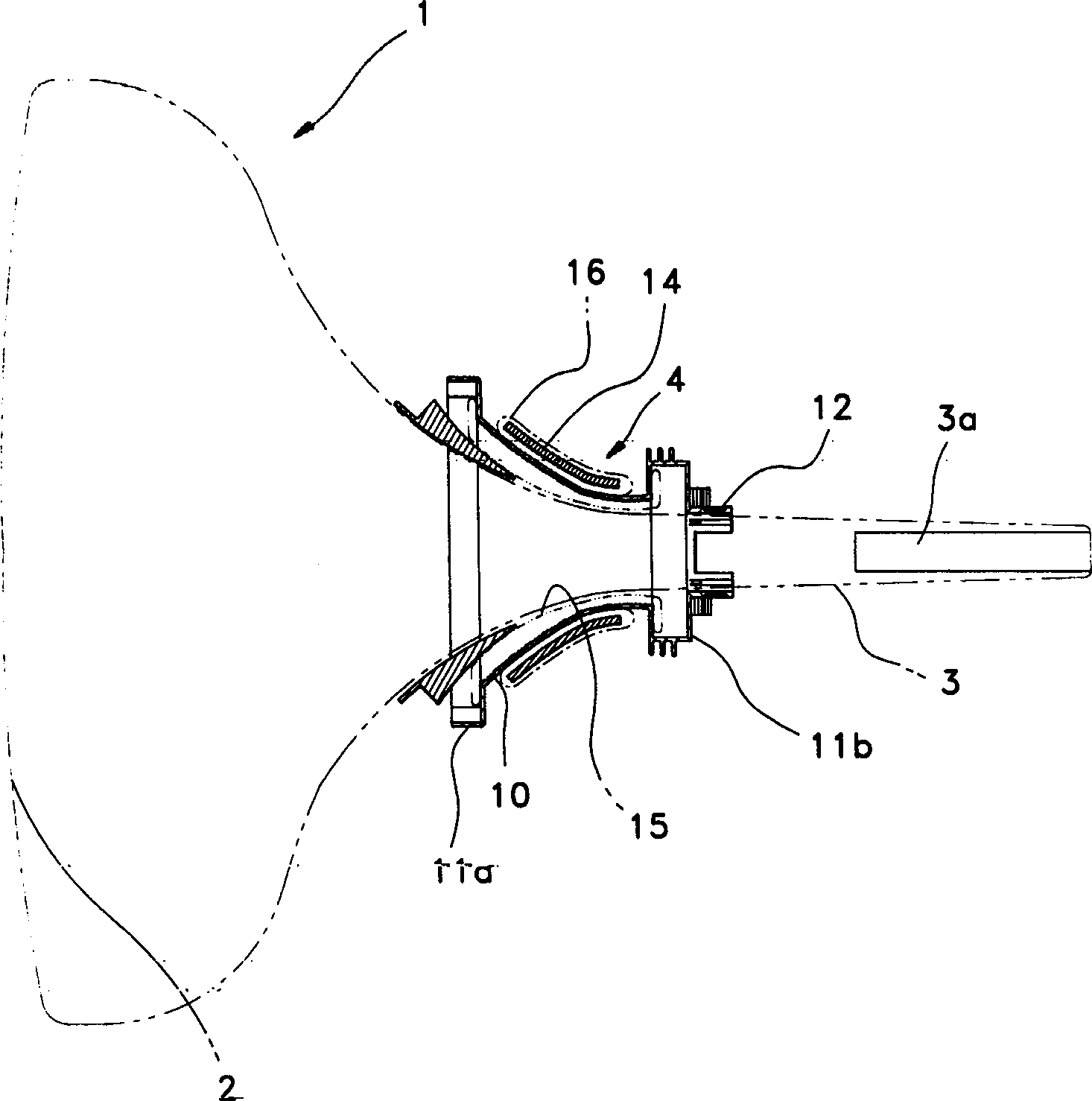
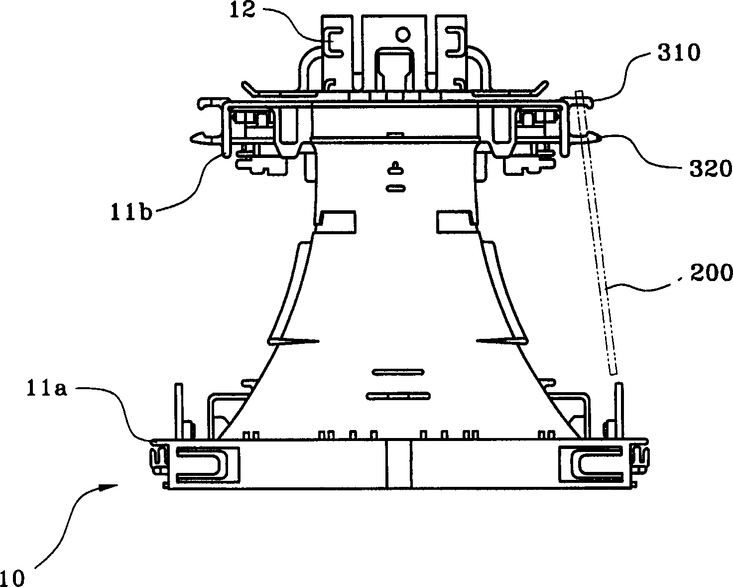
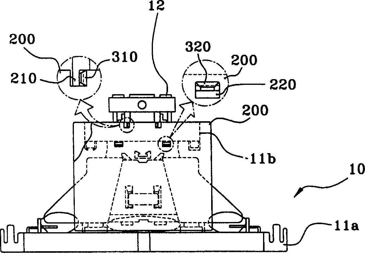
[0035] Figure 4 and Figure 5 It shows the installation state of the printed circuit board in the deflection yoke related to the present invention, and the following refers to figure 1 Further clarification has been made and the same symbols have been used for the same parts.

[0036] First, if figure 1 As shown, a coil splitter (10) substantially forming a conical shape is arranged in the deflection coil (4), and at this time, the coil splitter (10) is composed of one side of the screen (2) combined with the cathode ray tube (1) The screen portion (11a) of the large neck, the rear cover (11b), and the small neck of the electron gun portion (3) extended integrally from the center of the rear cover (11b) and connecte...


PUM


Abstract

The present invention provides a deflection yoke in which a structure for evenly supporting a printed circuit board is provided on the rear cover of the deflection yoke to prevent damage caused by assembly force when the printed circuit board is assembled on the rear cover.

Description

technical field [0001] The present invention relates to a deflection yoke, in particular to a deflection yoke which improves the support structure of a printed circuit board, thereby preventing damage caused by assembly force. Background technique [0002] The deflection coils usually used in TV receivers or display cathode ray tubes (CRT) are set to accurately deflect the three-color beams emitted by the electron gun to the fluorescent screen coated on the screen of the cathode ray tube. The most important factor in the magnetic device is that it deflects the electron beam emitted by the electron gun so that the electrical signal transmitted in time sequence reproduces the image on the screen of the cathode ray tube. [0003] That is, the deflection yoke means that as the electron beams emitted by the electron gun are directly projected onto the screen through high voltage, only the phosphor in the center of the screen can emit light, so it must be deflected so that the ele...

Claims


Application Information

Patent Timeline
Patent Type & Authority Applications(China)
IPC IPC(8): G09G1/04H01J29/70H01J29/76
CPCH01J29/70H01J29/76H01J2229/7038H01J2229/964
Inventor 杜铉植金圣云
Owner SAMSUNG ELECTRO MECHANICS CO LTD
Features
  • R&D
  • Intellectual Property
  • Life Sciences
  • Materials
  • Tech Scout
  • Unparalleled Data Quality
  • Higher Quality Content
  • 60% Fewer Hallucinations
Learn More