Oxygen sensor

An oxygen sensor, zirconia technology, applied in the field of oxygen sensors, can solve problems such as low gas response performance

Inactive Publication Date: 2003-11-05
KYOCERA CORP
View PDF0 Cites 28 Cited by
  • Summary
  • Abstract
  • Description
  • Claims
  • Application Information

AI Technical Summary

Problems solved by technology

However, due to the large size of the sensing element, the oxygen sensor cannot be heated quickly enough, which still exhibits low gas response performance

Method used


Image

  • Oxygen sensor
  • Oxygen sensor
  • Oxygen sensor

Examples


specific Embodiment approach

[0083] Detailed description of the invention (Experiment 1)

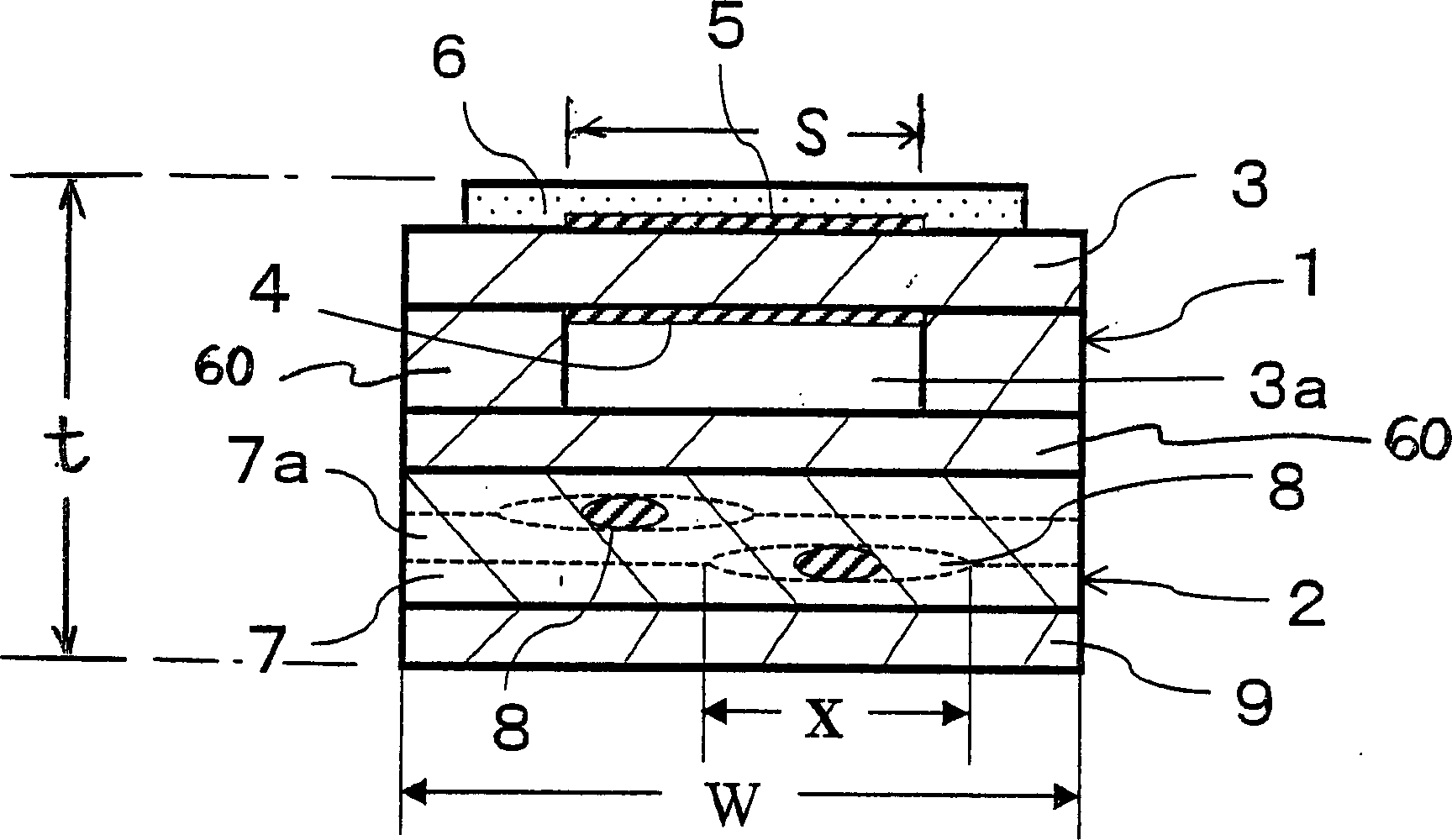
[0084] like figure 1 The lambda sensor shown is based on the following Figure 7 method to make.

[0085] First, an alumina powder with a purity of 99.9% containing 5 mol% of Y was prepared 2 O 3 Zirconia powder (containing 0.1% by weight of Si), platinum powder ① (average particle diameter: 0.1 μm) containing zirconia (containing 8% moL of yttrium oxide) by volume 30%, alumina powder containing 20% ​​by volume The platinum powder ②.

[0086] First, the polyvinyl alcohol solution is added to the above-mentioned zirconia powder to prepare a slurry, which is then extruded to form a zirconia green sheet 13, the thickness of which is 0.4 mm after sintering.

[0087] Then, the conductive paste containing platinum powder ① is printed on both surfaces of the green sheet 13 by screen printing, thereby forming electrode patterns 14, wire patterns 15 and electrode sheet patterns 16 serving as measuring electrodes and re...


PUM

PropertyMeasurementUnit
areaaaaaaaaaaa
widthaaaaaaaaaa
thicknessaaaaaaaaaa

Abstract

An oxygen sensor with a sensitive element comprising a long flat disc-shaped zirconia solid electrolyte matrix, a measuring electrode and a reference electrode formed of platinum, the measuring electrode and reference electrode being constructed at the end of the solid electrolyte matrix On the opposite surface so that they face each other, wherein the surface pole of the measuring electrode is 8 to 18 mm2, and the width w of the sensitive element is 2.0 to 3.5 mm at the end of the solid electrolyte matrix. Oxygen sensors exhibit excellent gas response performance, can be heated rapidly and are small in size.

Description

technical field [0001] The invention relates to an oxygen sensor, in particular to an oxygen sensor for controlling the ratio of air and fuel in an automobile engine. Background technique [0002] At present, the method adopted by modern automobile internal combustion engines for removing harmful substances such as CO, HC and NOx generated by the internal combustion engine is carried out by detecting the oxygen concentration in the exhaust gas, and based on the detected The amount of air and fuel supplied to the internal combustion engine is controlled based on the oxygen concentration value. [0003] As the detection device, a solid electrolyte oxygen sensor is mainly used at present, which includes a cylindrical tube, one end of which is sealed, and the tube is mainly composed of a solid electrolyte containing zirconia with oxygen ion conduction characteristics; and a pair of electrode layers disposed on the surfaces of the outer and inner layers of the cylindrical tube, ...

Claims


Application Information

Patent Timeline
Patent Type & Authority Applications(China)
IPC IPC(8): G01N27/407
CPCG01N27/4071
Inventor 秋山雅英德永浩治
Owner KYOCERA CORP
Why Eureka
Try Eureka