
Feedback modulating circuit

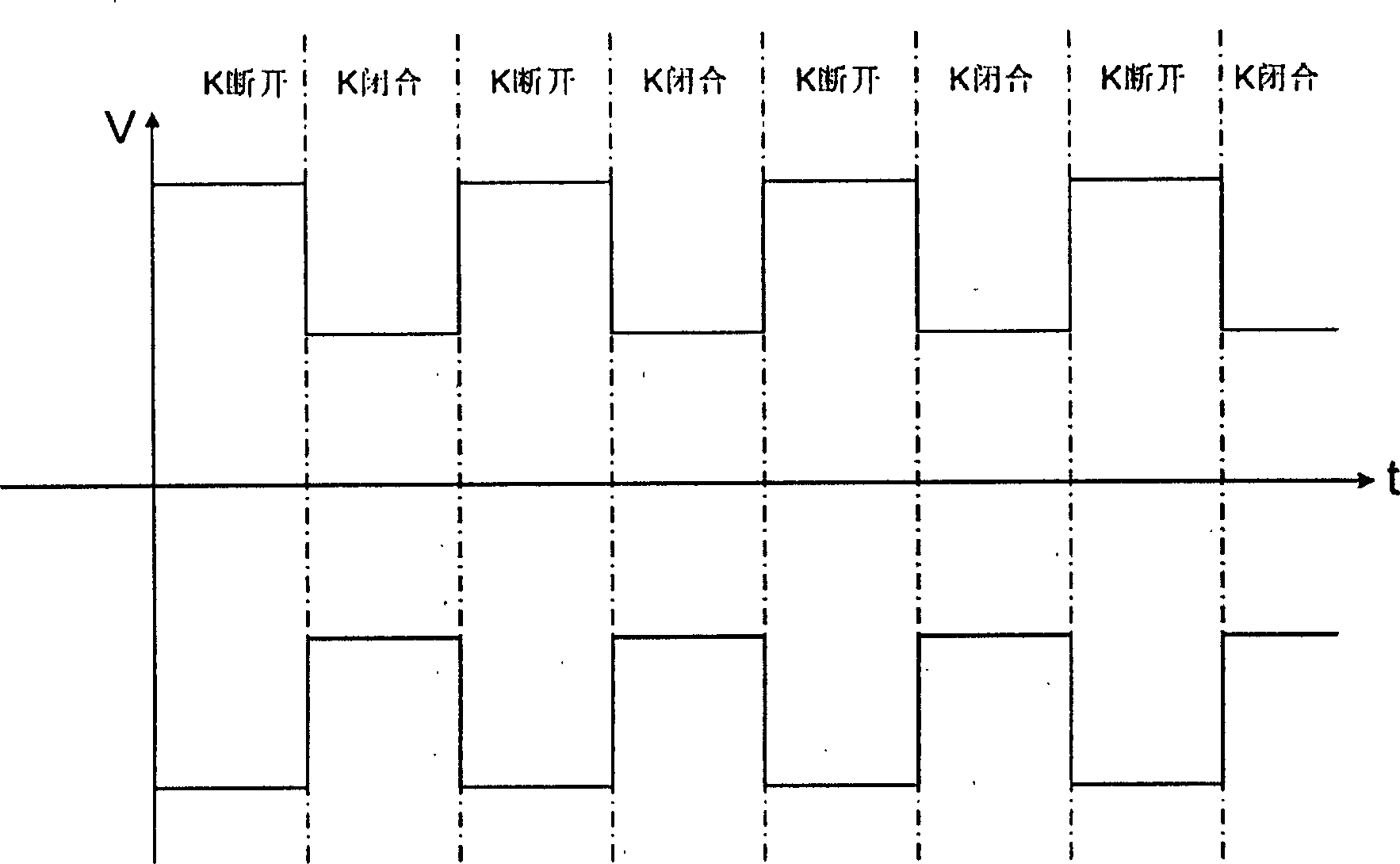
A modulation circuit and circuit technology, applied in the fields of modulation of electromagnetic waves, modulation, selection and arrangement of radio/induction links, etc., can solve the problems of affecting the power supply of the circuit, the effect of the effective coupling distance, and the demodulation of the data receiving device, so as to improve the working distance. , the effect of reducing the difficulty of design

Inactive Publication Date: 2003-12-03
SHANGHAI HUAHONG INTEGRATED CIRCUIT
View PDF0 Cites 4 Cited by
  • Summary
  • Abstract
  • Description
  • Claims
  • Application Information

AI Technical Summary

Problems solved by technology

The defect of this symmetrical ASK modulation method is that, due to the parallel analog load modulation, too large modulation amplitude will affect the power supply to the circuit, and too small amplitude will affect the demodulation of the data receiving device. As a result of optimization, the effective coupling distance is affected by

Method used


Image

  • Feedback modulating circuit
  • Feedback modulating circuit
  • Feedback modulating circuit

Examples


Embodiment Construction

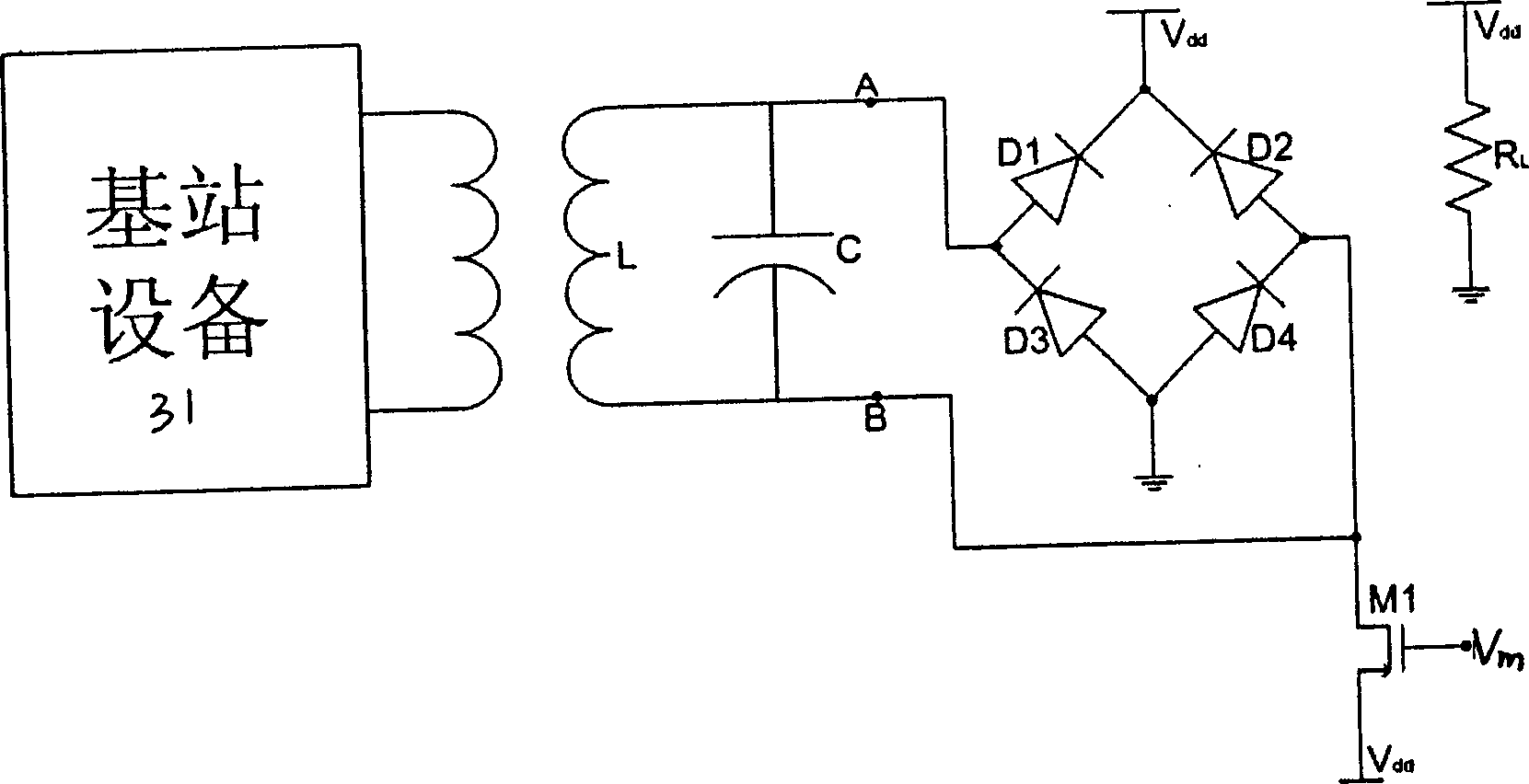
[0018] See image 3 , the resonant antenna L and the resonant capacitor C form the resonant circuit of the passive radio frequency device of the present invention, the rectifier diodes D1, D2, D3, D4 form the rectifier bridge stack, M1 is a modulation PMOS tube, R L Is the load resistance, Vm is the digital modulation signal. The two ends of the resonant tank are labeled A and B respectively. The resonant antenna L and the resonant capacitor C form a resonant circuit at the operating frequency, which is used for the passive radio frequency device to obtain energy, clock and data signals from the radio frequency field of the base station equipment 31, and transmit data signals to the base station equipment 31 through load modulation, thereby The input and output devices that constitute the modulation circuit, when the circuit is resonant, the energy that the passive radio frequency device obtains from the radio frequency field of the base station equipment 31 is the largest, o...


PUM


Abstract

A feedback modulation circuit for increasing the card reading distance by 1.5-2 times is composed of a resonant circuit consisting of resonant capacitor and resonant antenna for obtaining energy and clock and data signals from RF field of base station and transmitting data signals to base station, a rectifying bridge serially connected with said resonant circuit and consisting of 4 rectifying diodes, and a modulating PMOS transistor for modulating the load by data signals when data is transmitted to base station. Its advantages are simple circuit, and high modulating coefficient.

Description

technical field [0001] The invention belongs to a signal sending circuit of a passive radio frequency device, in particular to a feedback modulation circuit used therein. technical background [0002] For passive radio frequency devices, the transmission of signals is achieved by changing the equivalent load on the receiving equipment: that is, the passive radio frequency device obtains the energy and clock and data signals required for work from the electromagnetic field generated by the base station equipment. After processing, use the data to be sent back to the base station to control its own equivalent load with the change of the clock beat; the base station receiving equipment can detect the feedback generated by the load change, and reconstruct the transmission of the passive radio frequency device according to these feedbacks. The data. [0003] There are two main points in the design of passive radio frequency equipment: on the one hand, the operating voltage must ...

Claims


Application Information

Patent Timeline
Patent Type & Authority Applications(China)
IPC IPC(8): H04B1/00H03C7/00H04B1/04H04B1/18
Inventor 李向宏
Owner SHANGHAI HUAHONG INTEGRATED CIRCUIT
Learn More