Eureka AIR delivers breakthrough ideas for toughest innovation challenges, trusted by R&D personnel around the world.

Structure of slot feature for shadow mask

A slot and shadow mask technology, applied in the direction of discharge tubes, electrical components, electrode devices and related components, etc., can solve the problem of inability to form straight lines

Inactive Publication Date: 2003-12-24
LG PHILIPS DISPLAY KOREA CO LTD
View PDF0 Cites 0 Cited by
  • Summary
  • Abstract
  • Description
  • Claims
  • Application Information

AI Technical Summary

Problems solved by technology

But the problem caused is that the electron beam hitting the screen cannot form a perfect straight line after passing through the central area of ​​the shadow mask

Method used


Image

  • Structure of slot feature for shadow mask
  • Structure of slot feature for shadow mask
  • Structure of slot feature for shadow mask

Examples


Embodiment Construction

[0047] Detailed description of the preferred embodiment

[0048] Preferred embodiments of the present invention will now be described in detail, examples of which are illustrated in the accompanying drawings.

[0049] Figure 8A is a schematic diagram showing a shadow mask employing the mask slot feature of the present invention; Figure 8B is to pass Figure 8A Schematic illustration of the shape of the electron beam after the slot.

[0050]The shadow mask 30 includes a central slot 30a formed in a central area thereof, and slots 30b and 30c formed in peripheral areas other than the central area thereof in consideration of the fact that the electron beam 6 is distorted after passing through the shadow mask 30.

[0051] Generally, when the electron beam moves toward the peripheral area, the shape of the electron beam 6 is significantly distorted in its central area according to the incident direction.

[0052] That is, in the present invention, with Figure 6A and 6C Dif...


PUM


Abstract

A structure of a slot feature for a shadow mask in which, on the assumption that the width at the point of 1 / 2 in a vertical direction in the feature of slots of the shadow mask is 'Sw', horizontal distances from a virtual vertical line passing an apex of a concave portion of a slot at a marginal portion to a protrusion portion formed at both upper and lower sides on the basis of the width Sw line are 'M' and 'N', and angles inclined in the direction of the protrusion portion from the virtual straight line passing the apex of the curved protrusion portion formed at the opposite side of the concave portion are 'P' and 'Q', there are at least one and more mask slot satisfying a formula of M > 0, N > 0, P > 0 DEG , Q > 0 DEG . The shape of electron beams by positions on the screen are identical to each other, and the shape of electron beam at the left and right sides of marginal portion can be maintained in a straight line in the vertical direction. Accordingly, a purity margin of the electron beam can be increased and brightness characteristics can be improved, and thus, a quality of color reproduction can be heightened.

Description

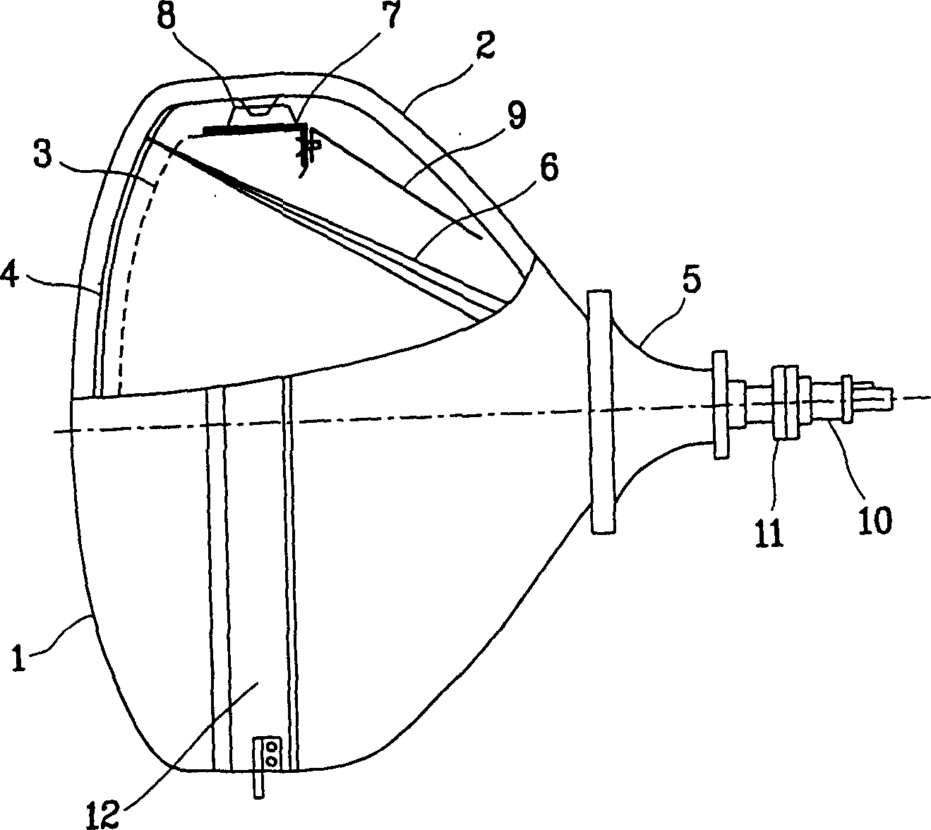
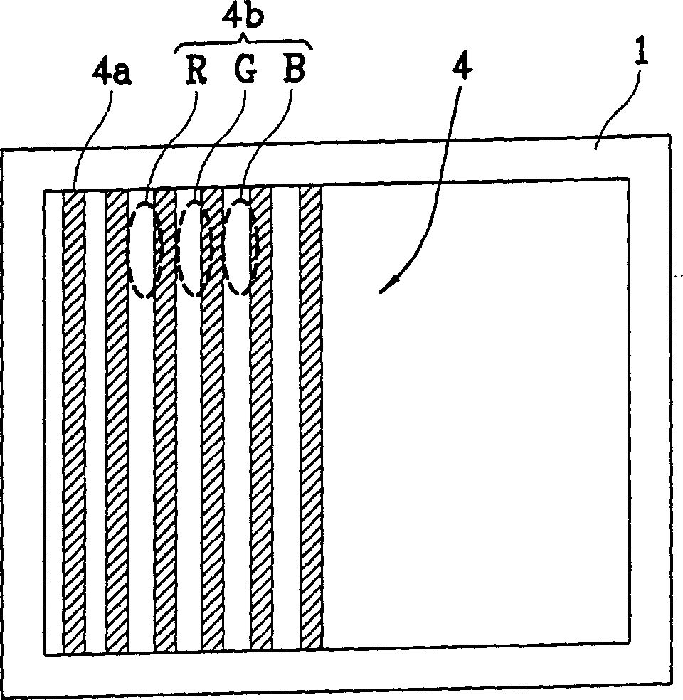
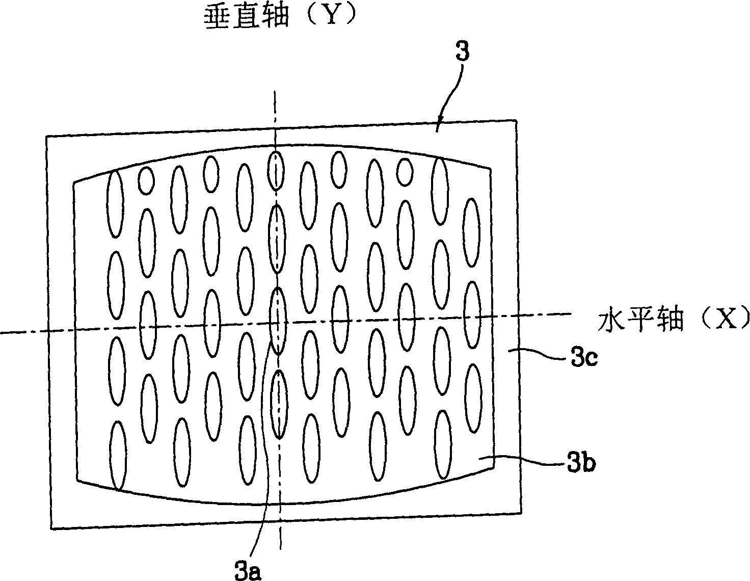
field of invention [0001] The present invention relates to a shadow mask for a cathode ray tube (CRT), and more particularly, to the configuration of the slot features of the shadow mask to improve the purity margin by emitting a shaped electron beam onto the phosphor screen on the rear side of the screen. margin) and brightness properties. Background technique [0002] Generally, a shadow mask is installed inside a Braun tube for a TV or a monitor to perform color classification so that electron beams generated by an electron gun are emitted onto the surface of phosphors required for a phosphor screen. [0003] Such as figure 1 As shown, the CRT includes: a fluorescent surface 4, which is connected with a front glass called a screen 1 and a rear glass called a funnel 2, which is excited inside the screen 1; an electron gun 10 is used to excite the fluorescent surface A source of electron beam 6; a shadow mask 3, sorting colors to excite specific phosphor surfaces; and a f...

Claims


Application Information

Patent Timeline
Patent Type & Authority Applications(China)
IPC IPC(8): H01J29/07H01J29/80
CPCH01J29/076H01J2229/0755H01J29/07
Inventor 都基埙
Owner LG PHILIPS DISPLAY KOREA CO LTD
Why Eureka
Eureka Blog
Learn More