Method of rolling worm gear and worm gear

A processing method and technology of worm, applied in the field of worm, can solve the problem of inability to completely prevent penetration feed and the like

Inactive Publication Date: 2003-12-24
NISSEI CO LTD
View PDF2 Cites 18 Cited by
  • Summary
  • Abstract
  • Description
  • Claims
  • Application Information

AI Technical Summary

Problems solved by technology

[0007] However, even with such a spindle tilting mechanism, in workpieces such as worms whose diameter changes greatly from the start of machining to the end of machining, the occurrence of through feed cannot be completely prevented, and it becomes the occurrence of machining errors.

Method used


Image

  • Method of rolling worm gear and worm gear
  • Method of rolling worm gear and worm gear
  • Method of rolling worm gear and worm gear

Examples


Embodiment Construction

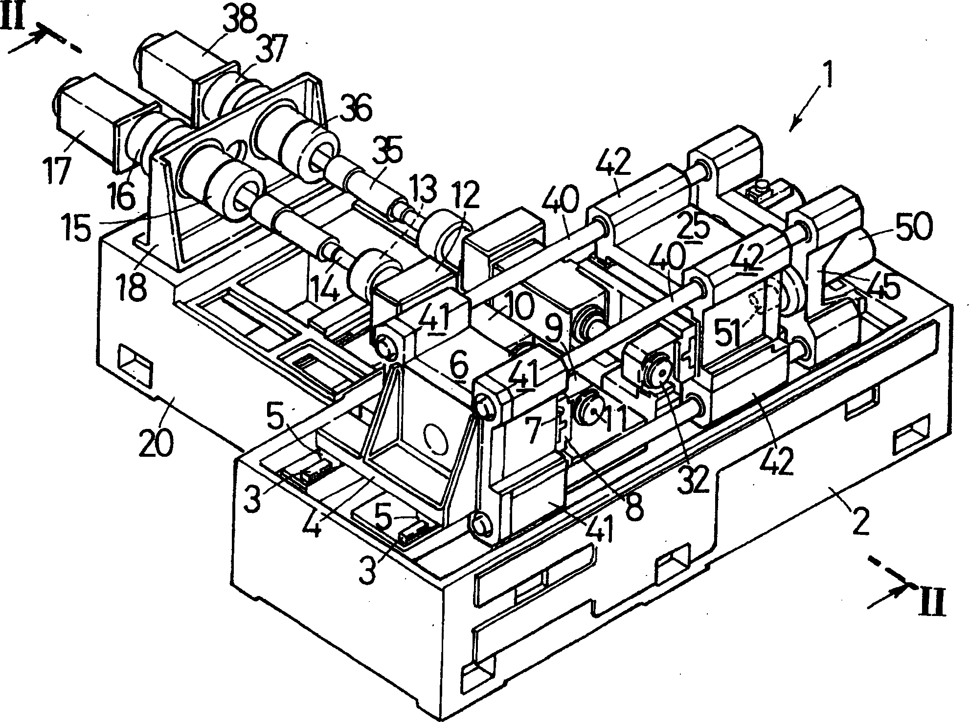
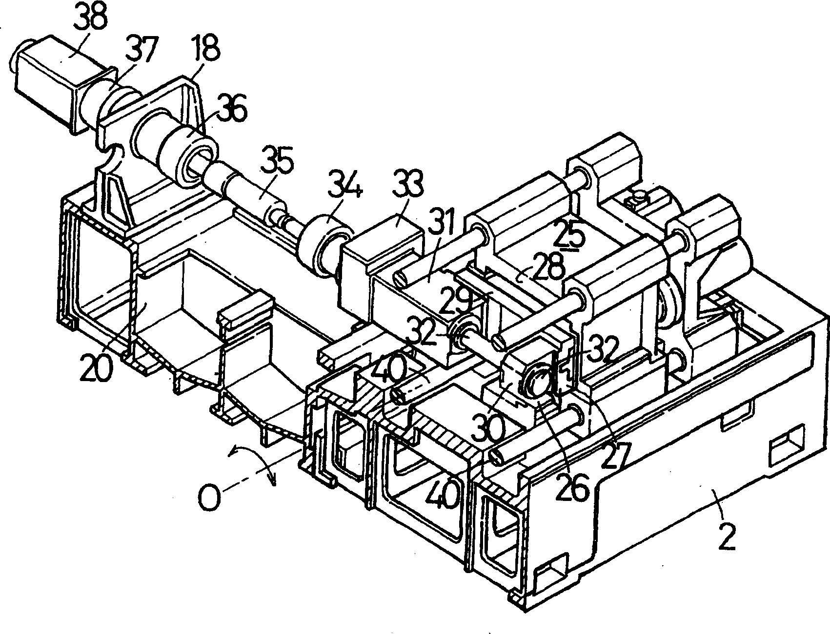
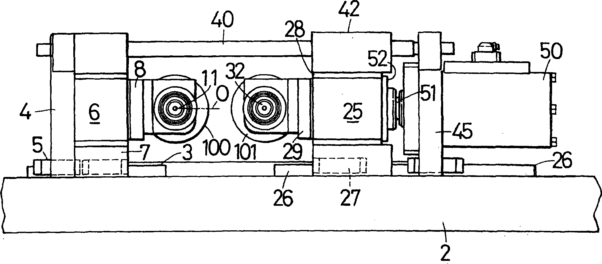
[0037] Next, examples embodying the present invention will be described. figure 1 It is an overall perspective view showing a rolling machine for rolling the worm of the present invention. figure 2 yes figure 1 Partial sectional view of II-II. image 3 is the front view of the rolling mill. Figure 4 is a cutaway top view. The rolling mill 1 is a circular rolling mill for plastically deforming a billet by arranging cylindrical molds facing each other. In a common round die rolling machine, a movable die to be driven to rotate and a fixed die driven to rotate by it are arranged opposite to each other with their rotation axes parallel to each other, and a billet is placed between them.

[0038] The rolling machine 1 for machining a worm according to the present invention synchronously drives and rotates two round dies in the same rotation direction during machining. The detailed structure will be described below. The base 2 constitutes the body of the rolling mill 1, and ...


PUM

PropertyMeasurementUnit
radiusaaaaaaaaaa

Abstract

A method of forming a worm gear by rolling to reduce the number of working processes while sufficiently assuring a gear accuracy, comprising the step of positioning a work material between a first rolling die (100) and a second rolling die (101) by the rotation of the rolling dies and a servo-motor (76) for feeding the work material, wherein the lead angle of the worm gear varies to produce a step during form rolling when the lead angle is large enough to produce a large difference between a finished diameter and a material diameter, a slide table (55) is slid freely on a feed table (53) and detected by a detection sensor when the step occurs by the lead angle of the first rolling die (100), second rolling die (101), and the work since the slide plate (55) is allowed to slid freely on the feed table (53), the rotations of the first rolling die (100) and the second rolling die (101) are stopped, the reverse movement of the slide plate (55) is also started to start the rolling simultaneously when the first rolling die (100) and the second rolling die (101) are started to rotate reversely and the same steps are repeated for rolling.

Description

technical field [0001] The invention relates to a rolling processing method of a worm and the worm. More specifically, it relates to a worm rolling method used for rolling a worm for driving a steering handle of an automobile, and a worm rolled by the rolling method. Background technique [0002] As an electric power steering device for a vehicle, there is known a type in which the rotational output of an electric motor is decelerated by a worm mechanism, and the output shaft connected to the steering wheel is boosted; In the power steering device, the combination of metal cylindrical worm and resin worm wheel is used as the type of worm gear (such as Japanese Patent Laid-Open No. 9-24855.) [0003] Due to precision requirements, this metal worm needs heat treatment and grinding after turning the hardened steel. In the case of lathe processing, it is cut with a turning tool; however, in order to improve productivity, a conical milling cutter is used, and the axis of the mi...

Claims


Application Information

Patent Timeline
Patent Type & Authority Applications(China)
IPC IPC(8): B21H5/00F16H55/22
CPCF16H55/22B21H5/005Y10T29/49471B21H5/02
Inventor 新仏利仲吉泽稔天野秀一伊藤健治
Owner NISSEI CO LTD
Why Eureka
Try Eureka