Magnetic suspension shock absorber

A shock absorber and magnetic levitation technology, which is applied in the direction of spring/shock absorber, magnetic spring, spring, etc., can solve the problems of high noise, short life, poor vibration reduction effect, etc.

Inactive Publication Date: 2003-12-31
杨子余
View PDF0 Cites 12 Cited by
  • Summary
  • Abstract
  • Description
  • Claims
  • Application Information

AI Technical Summary

Problems solved by technology

[0003] In order to overcome the disadvantages of existing shock absorbers such as complex structure, poor vibration damping effect, short life and high noise, the present invention provides a magnetic suspension shock absorber with simple and reasonable structure, convenient processing and use, good vibration damping effect and long life

Method used


Image

  • Magnetic suspension shock absorber
  • Magnetic suspension shock absorber
  • Magnetic suspension shock absorber

Examples


Embodiment Construction

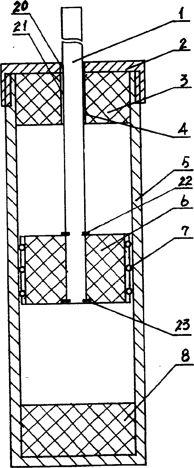
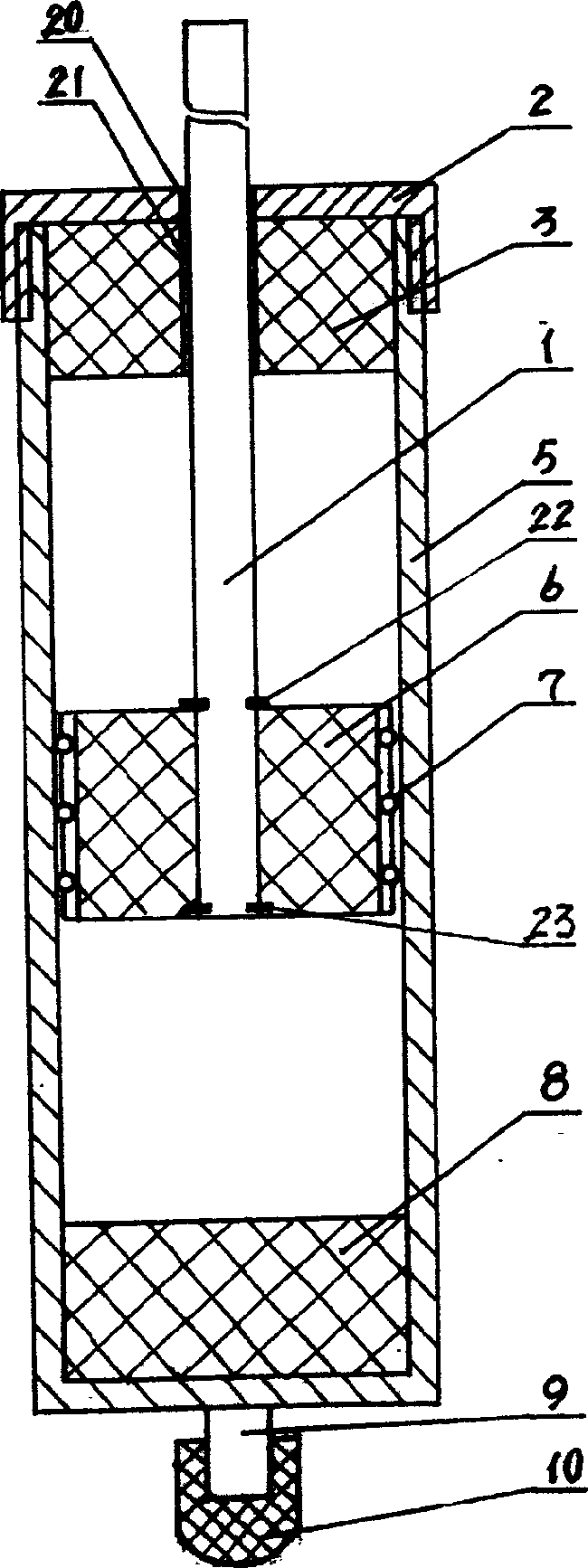
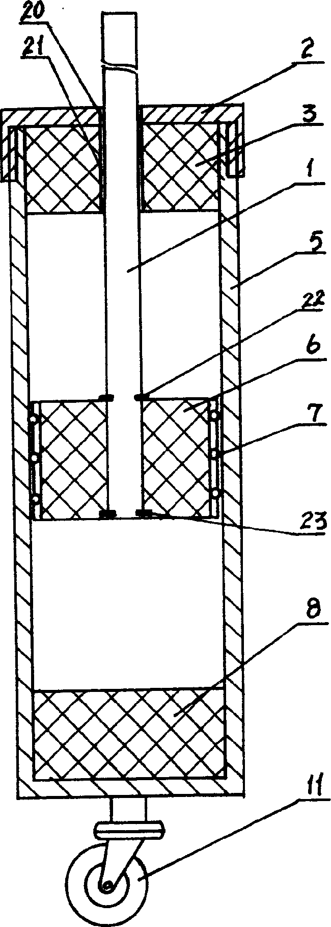
[0010] figure 1 As shown, it is the first specific embodiment of the magnetic suspension shock absorber of the present invention, which includes a movable rod 1, an outer cylinder 5 and a fixed cover 2, the fixed cover 2 is provided with a central hole 20 and is fixed on the outer cylinder 5, and the outer cylinder 5 is fixed on the outer cylinder 5. The inner bottom of cylinder 5 is provided with lower magnet 8, and the upper opening of outer cylinder 5 is provided with upper magnet 3, and upper magnet 3 is provided with central hole 4, is provided with suspension magnet 6 between upper and lower magnet 3,8, and upper Magnet 3 and levitation magnet 6 as well as levitation magnet 6 and lower magnet 8 are arranged in phase with each other, movable rod 1 passes through fixed cover center hole 20 and upper magnet center hole 21 and is fixedly connected with levitation magnet 6, and movable rod 1 is connected with fixed cover Between the center hole 20 and the upper magnet center ...


PUM


Abstract

The magnetic suspension damper includes a movable rod, an outer barrel, fixed cover with central hole on the outer barrel, upper magnet with central hole in the upper mouth of the outer barrel, lower magnet in the bottom of the outer barrel, and suspended magnet between the upper and the lower magnets. All the magnets have magnetic poles set in phase, and the movable rod is made to pass through the central hole in the fixed cover and that in the upper magnet and to connect with the suspended magnet. The suspended magnet is provided with friction-reducing roller sheet for contact with inside wall of the outer barrel. The said structure makes the magnets produce mutual expelling force and the suspended magnet be affected by magnetic resistance. The present invention has high damping effect.

Description

1. Technical field [0001] The invention relates to a shock absorber, in particular to a magnetic suspension shock absorber designed using the principle of permanent magnets repelling each other with the same sex and attracting each other with opposite sexes. 2. Background technology [0002] The currently used vibration damping technologies can generally be divided into pneumatic damping, hydraulic damping and mechanical damping, or a combination of the above three methods; pneumatic damping and hydraulic damping require additional control devices to control. To achieve the vibration damping effect, there are complex structures, high machining accuracy requirements, and high price. Leakage is prone to occur during use, resulting in a decrease in vibration damping effect. After damage, it is difficult to repair, and generally needs to be updated. Although the structure of mechanical vibration damping is relatively simple, the processing is relatively conv...

Claims


Application Information

Patent Timeline
Patent Type & Authority Applications(China)
IPC IPC(8): F16F6/00
Inventor 杨子余
Owner 杨子余
Why Eureka
Try Eureka