
Physical insulated switchboard and insulating control method

A physical isolation and switch technology, applied in the field of computer networks, can solve the problems of switching speed and stability of internal and external networks, increasing network construction costs, and complexity of technical implementation, ensuring speed and stability, saving manpower and material resources, The principle is simple and clear

Inactive Publication Date: 2003-12-31
BOE TECH GRP CO LTD
View PDF0 Cites 3 Cited by
  • Summary
  • Abstract
  • Description
  • Claims
  • Application Information

AI Technical Summary

Problems solved by technology

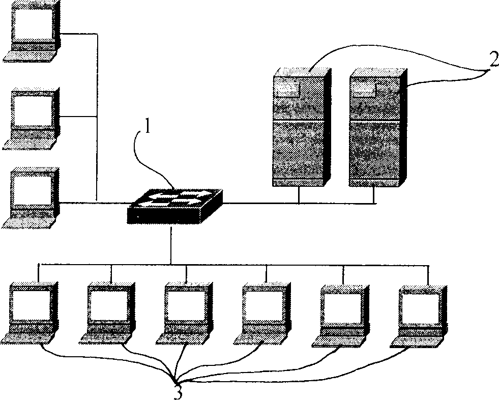
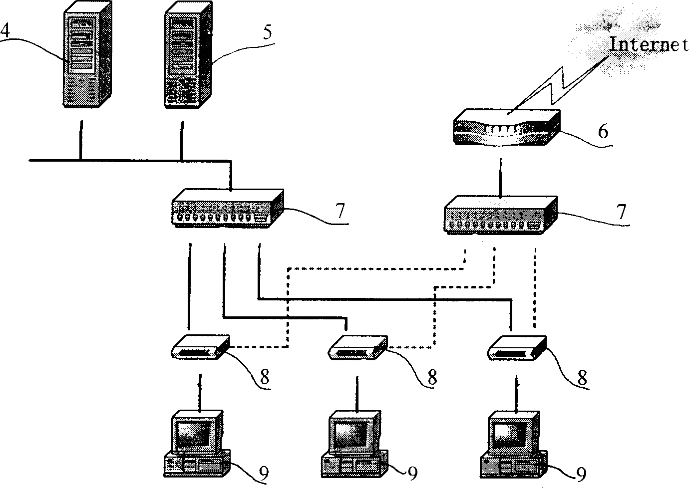
[0010] 3. The physical isolator 8 divides the network into two for physical isolation so that they cannot communicate with each other
The complexity of technical implementation has greatly reduced the speed and stability of internal and external network switching
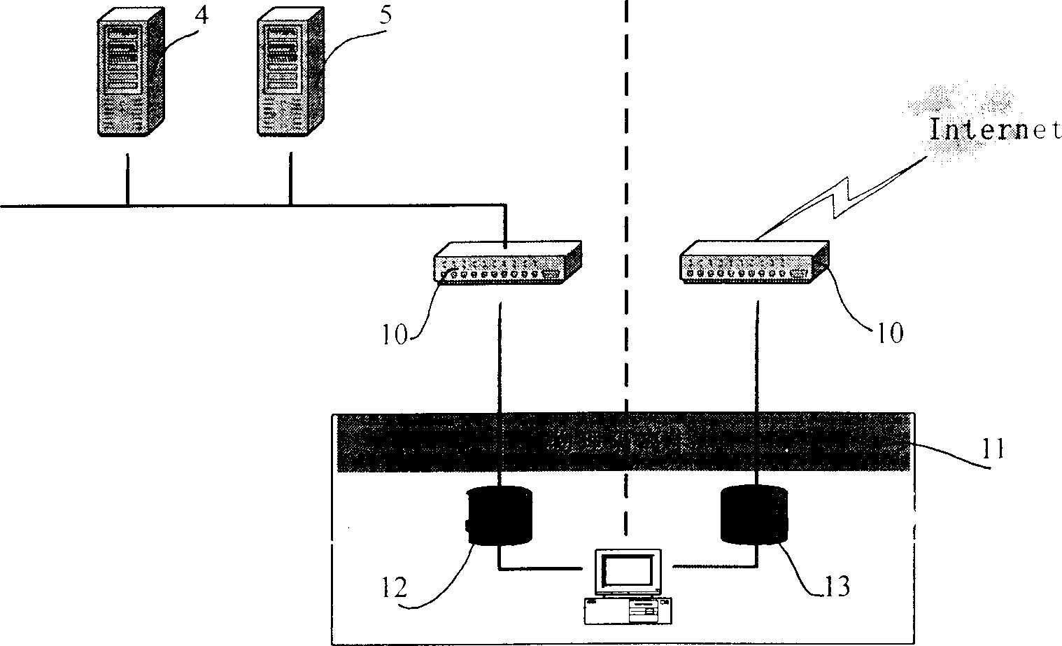
[0020] It can be seen that it is difficult for traditional single physical isolation products to achieve real physical isolation. To achieve real physical isolation, not only the effect of dual network physical isolation must be achieved, but also the dual hard disk physical isolation must be achieved.
In response to this demand, for a network environment with a single network cable, secondary wiring engineering may be required, which is not only time-consuming and labor-intensive, but more importantly, increases the cost of network construction
The installation of hardware devices such as dual hard disks and network cards not only increases the cost, but also leaves many hidden dangers for future system maintenance and upgrades.
Therefore, the traditional physical isolation solution is not a cost-effective solution from the perspective of economy and security.

Method used


Image

  • Physical insulated switchboard and insulating control method
  • Physical insulated switchboard and insulating control method
  • Physical insulated switchboard and insulating control method

Examples


Embodiment Construction

[0047] The invention is based on the network physical isolation of the thin client system. In the thin client / server system architecture, data centralization and security are its biggest features. All application software of the thin client runs on the server, and all data files of the thin client are stored on the server. Since the thin client has no local hard disk and data peripherals, as long as the data security of the server is ensured (physical isolation), the It can realize the security isolation of the whole system internal and external network.

[0048] The invention includes the switch function and the physical isolation switching function of the client computer and the server.

[0049] The switch part of the present invention can be with common network switch structure (as Image 6 shown) are consistent. its composition see Figure 7 As shown, it is composed of a control processor connected to a MAC port of a client network card, a route listening engine, an ad...


PUM


Abstract

The invention discloses a network physical isolation switchboard wherein the control processor port of the network switchboard is connected to a switch module, the inner server port and the outer server port are connected to the physically isolated logic NOT switch module ports, the client machine is connected to the switchboard network port, the control processor control logic is connected to the switch module control end via. a switch logic module, the switch logic module is arranged to switch the module actions according to processing of the processor. Further, the control processor port of the switchboard is also connected to a universal I / O port and the distributed logical module, wherein the universal I / O port provides standard input / output ports for the allocated static control information of the switchboard, the distributed logic module is used to store the switchboard static control information, the switching control processor switches the port operating status, amends routing information and switching logic according the control logic.

Description

technical field [0001] The invention relates to a network security and data exchange technology, in particular to a switch capable of realizing network physical isolation and an isolation control method. It belongs to the technical field of computer network. Background technique [0002] In recent years, the information industry is developing at a speed that astonishes the world, and the development of the information industry has greatly improved the comprehensive competitiveness of our country. But the popularization of information network has also brought us new security threats, such as network data thieves, hacker attacks, virus publishers, and even leakers inside the system, which have caused us serious losses. Therefore, information security must be paid attention to and strengthened. [0003] "If there is no physical connection to the network, the threat to network security will be truly limited." Article 6 of the "(Computer Information System International Network...

Claims


Application Information

Patent Timeline
IPC IPC(8): G06F12/14G06F12/16
Inventor 王占宏韩大伟
Owner BOE TECH GRP CO LTD
Learn More