Plane top type pass band WDM device

A wavelength division multiplexing device, flat-top technology, applied in the direction of wavelength division multiplexing system, electrical components, optical waveguide coupling, etc., can solve the problems of uncertain results, increasing device size, time-consuming, etc., to achieve no widening The effect of imaging width and device compact structure

Inactive Publication Date: 2004-01-07
ZHEJIANG UNIV
View PDF3 Cites 1 Cited by
  • Summary
  • Abstract
  • Description
  • Claims
  • Application Information

AI Technical Summary

Problems solved by technology

In addition, most of the planarization designs broaden the image on the imaging surface, so it is required to increase the size of the device to expand the distance between adjacent output channels, which is very unfavorable for high-channel wavelength division multiplexing devices
Using the IFFT algorithm to achieve spectral response flattening by fine-tuning the grating is time-consuming and has the disadvantage of uncertain results

Method used


Image

  • Plane top type pass band WDM device
  • Plane top type pass band WDM device
  • Plane top type pass band WDM device

Examples


Embodiment Construction

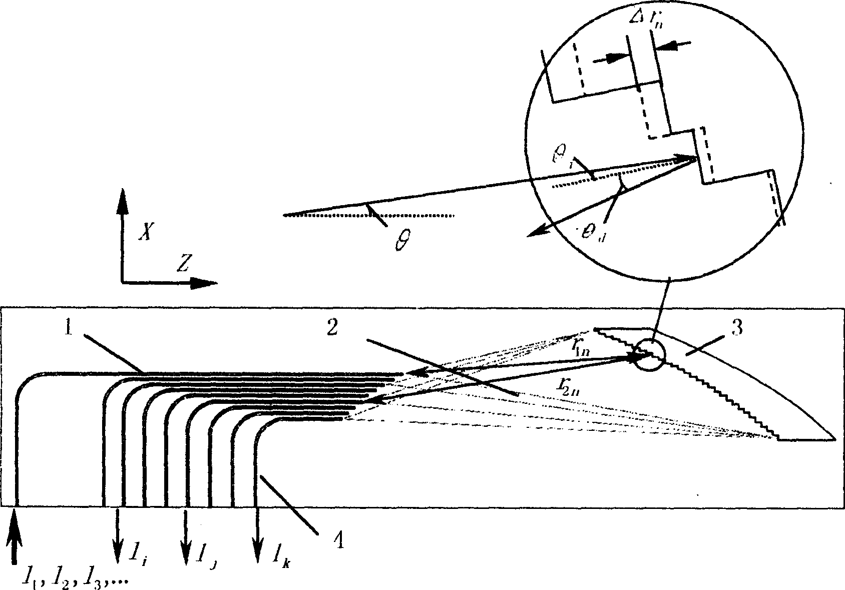
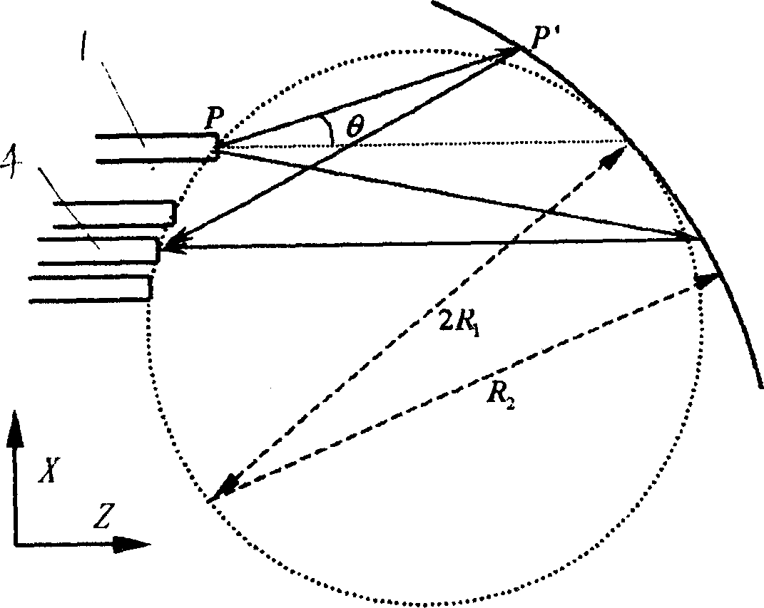
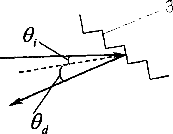
[0029] With reference to accompanying drawing: the present invention comprises input waveguide 1, free propagation zone 2, diffraction grating 3 and output waveguide 4, input waveguide 1 and output waveguide 4 are positioned at one side of free propagation zone 2, and diffraction grating 3 is positioned at the other side of free propagation zone 2 On one side, there is a certain phase difference between the different teeth of the diffraction grating 3. The center position of each grating tooth is slightly trimmed on the original basis. The trimming direction is generally perpendicular to the grating tooth surface. The trimming of the nth grating tooth center position The magnitude satisfies the formula: r 1n + r 2n = r 10 + r 20 +n·m·λ+f(θ n ) / k; where and is the wave vector of light in the free propagation region.

[0030] According to the Kirchhoff-Huygens diffraction formula, the field distribution on the imaging surface of the grating can be written as ...


PUM


Abstract

This invention relates to a WDM device with flattop passband including an input waveguide, free propagation zone, diffraction grating and an output waveguide, the inputted and output waveguides are at a side of the free propagation zone, the diffraction grating is at the other side with phase difference between different teeth characterizing in that each grating tooth central place is slightly rectified on its original basis, the rectified direction is verticle to the grating tooth face, the rectified amplitude meets the formula: r1n+r2n=r10+r20+n.m.lambda+f(thetan)/k, in which, k is the wave vector of light in free propagation zone, capable of getting the spectral response with flat pass-band, steep edge and low crosstalk.

Description

technical field [0001] The invention belongs to the technical field of optical communication wavelength division multiplexing, in particular to a wavelength division multiplexing device with a flat-top passband. Background technique [0002] Wavelength division multiplexing / demultiplexing technology is the key technology of modern optical fiber communication technology. Wavelength division multiplexing / demultiplexing refers to the combination of light of different wavelengths into composite light and the separation of light of different wavelengths in the composite light through special technology. A wavelength division multiplexing (demultiplexing) device is a device that implements wavelength division multiplexing / demultiplexing technology. Diffraction etched grating is a very typical integrated wave division multiplexing device. Compared with other wave division multiplexers, diffraction etched grating has the advantages of high integration, small si...

Claims


Application Information

Patent Timeline
Patent Type & Authority Applications(China)
IPC IPC(8): G02B6/26H04B10/25H04J14/02
Inventor 石志敏何赛灵
Owner ZHEJIANG UNIV
Why Eureka
Try Eureka