
Cooling mechanism and cooling method for driving element of injection moulding machine

An injection molding machine and injection molding technology, applied in the cooling mechanism and cooling field, can solve the problems of corrosion of cooling fluid flow path, large-scale manufacturing cost of injection molding machine, reduction of rated heat output of electric drive parts, etc.

Inactive Publication Date: 2004-01-21
SUMITOMO HEAVY IND LTD
View PDF0 Cites 4 Cited by
  • Summary
  • Abstract
  • Description
  • Claims
  • Application Information

AI Technical Summary

Problems solved by technology

[0009] However, as far as the forced air cooling method is concerned, the electric drive is only forced to be air-cooled by a fan, etc., so the heat generated during the operation of the electric drive cannot be fully released, so it is necessary to reduce the electric drive. Rated heat output of parts
[0010] In addition, in terms of the cooling fluid passage method, additional large-scale equipment is required, which will lead to an increase in the size of the injection molding machine and increase in manufacturing costs.
Furthermore, if water is used as the cooling fluid, the water quality will cause corrosion inside the cooling fluid flow path, and sometimes the water temperature will cause condensation due to air temperature, which will cause problems such as motor short circuit

Method used


Image

  • Cooling mechanism and cooling method for driving element of injection moulding machine
  • Cooling mechanism and cooling method for driving element of injection moulding machine
  • Cooling mechanism and cooling method for driving element of injection moulding machine

Examples


Embodiment Construction

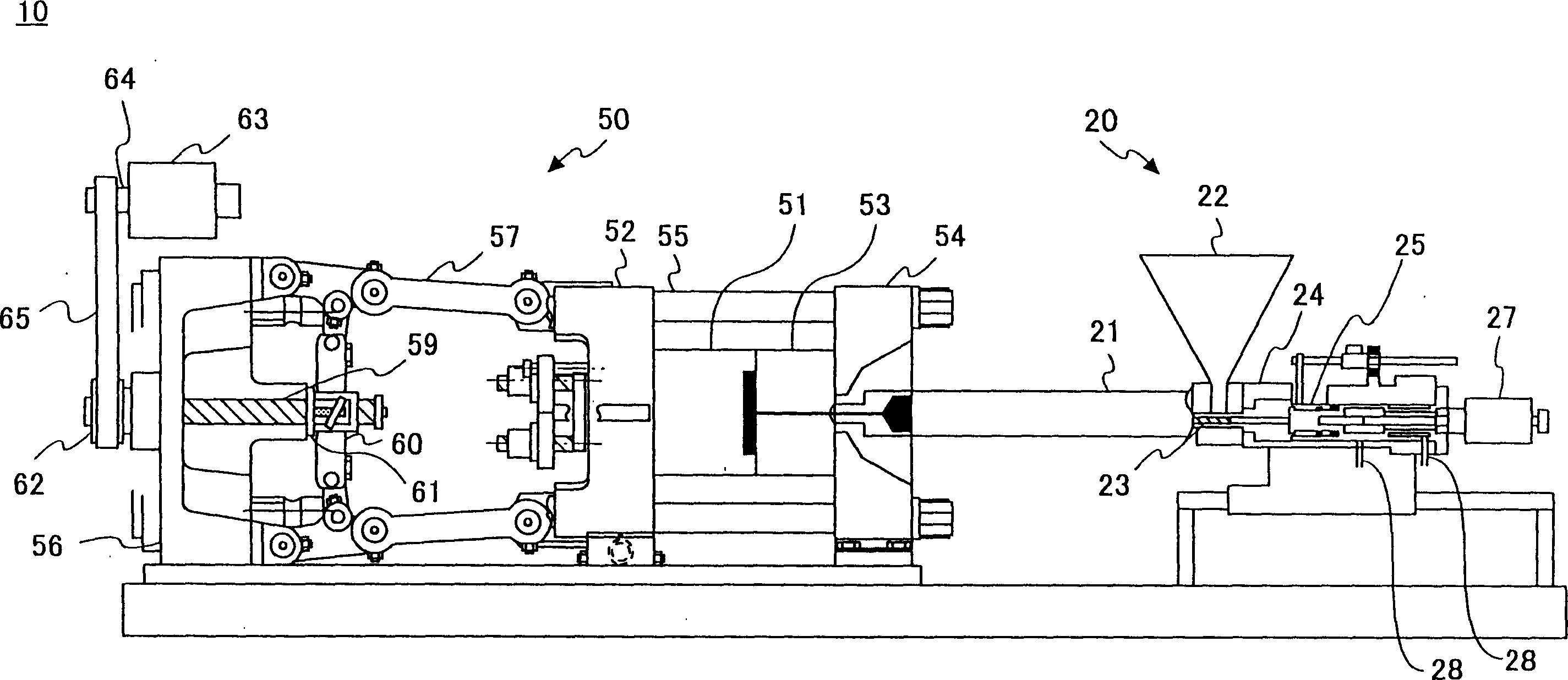
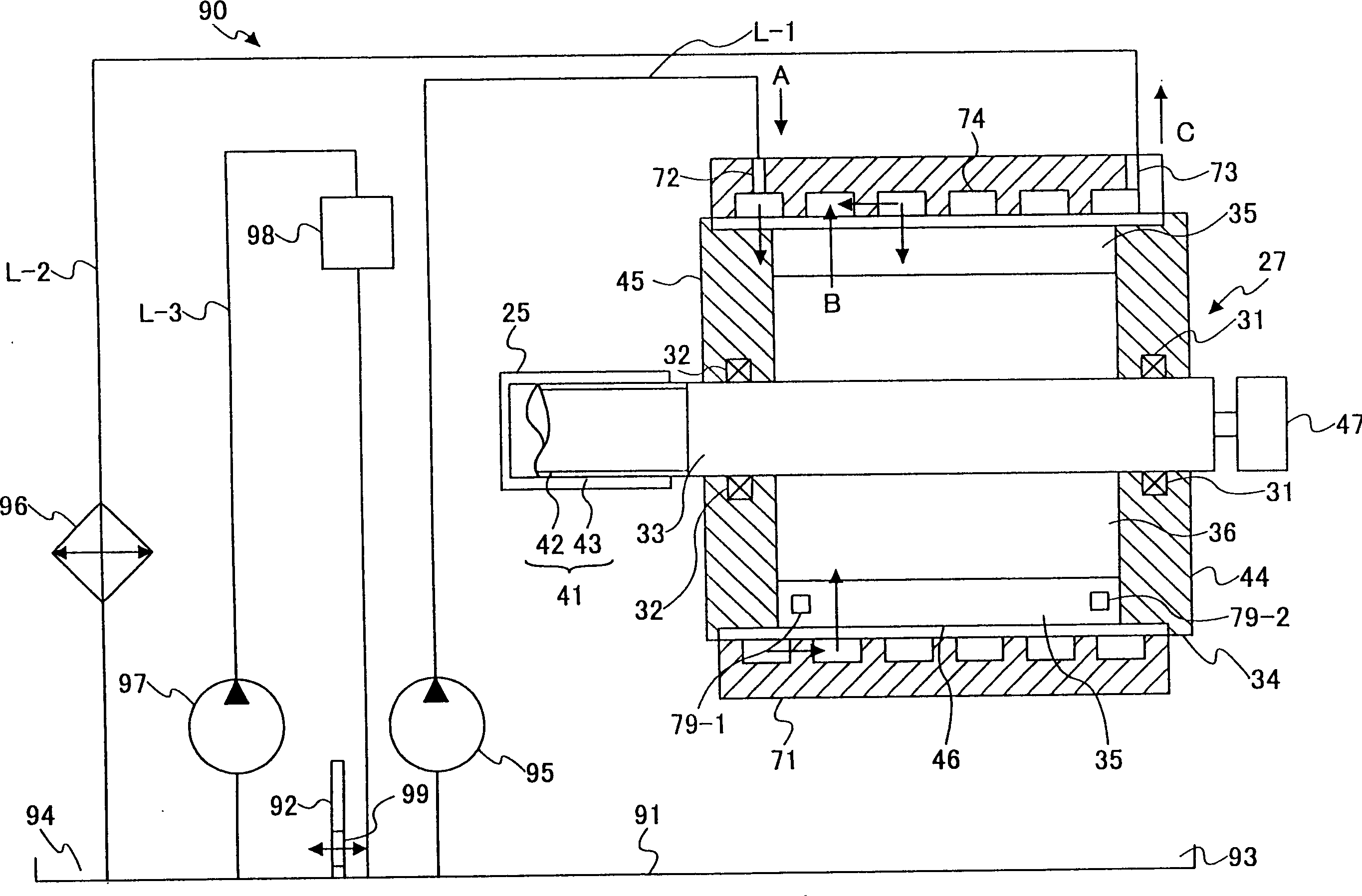
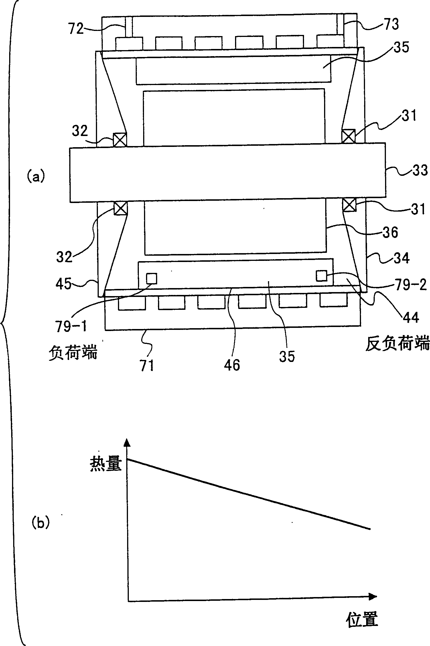
[0018] Refer to the attached below figure 1 To 4 illustrate the embodiments of the present invention.

[0019] figure 1 The basic structure of an injection molding machine according to an embodiment of the present invention is shown. See figure 1 The injection molding machine 10 is a hybrid injection molding machine equipped with an electric drive and a work piece that operates by supplying a working fluid.

[0020] The injection molding machine 10 includes an injection device 20 and a mold clamping device 50.

[0021] The injection device 20 includes a heating cylinder 21, and a hopper 22 is arranged at the heating cylinder 21. In addition, the screw rod 23 is arranged in the heating cylinder 21 so as to freely rotate and advance and retreat. An injection cylinder 24 is provided at the rear of the screw rod 23.

[0022] The injection cylinder 24 is provided with an injection plunger 25 that can move linearly. By supplying hydraulic oil from the oil passage 28, the injection p...


PUM


Abstract

A cooling mechanism for cooling an electric driving part of an injection molding machine, includes a cooling part for cooling the electric driving part; and an actuating part actuated by being supplied an actuating fluid, the actuating fluid being in fluid communication with the cooling part. The actuating fluid may be used as a cooling fluid for cooling the electric driving part.

Description

Technical field [0001] The present invention relates to a cooling mechanism and a cooling method for a driving part of an injection molding machine, and in particular to a cooling mechanism for a driving part of a hybrid injection molding machine (which includes an electric driving part such as a motor and a work part that operates by supplying a working fluid) And cooling method. Background technique [0002] In the injection molding machine, the resin heated and melted in the heating cylinder is injected under high pressure and filled into the mold cavity of the mold device, and it is cooled and solidified in the mold cavity to become a molded product. [0003] The above-mentioned injection molding machine includes a mold device, a mold clamping device, and an injection device. The mold device includes a fixed mold and a movable mold. The closing, clamping, and opening of the mold device are performed by moving the movable mold forward and backward by the clamping device. In ad...

Claims


Application Information

Patent Timeline
Patent Type & Authority Applications(China)
IPC IPC(8): B29C45/50B29C45/72B29C45/82
CPCB29C45/82B29C45/5008B29C2045/7271B29C2045/7285B29C45/72
Inventor 寺田真司
Owner SUMITOMO HEAVY IND LTD
Learn More