Medical refuse pyrolytic-gasification incineration apparatus

A technology for pyrolysis and gasification, medical waste, applied in incinerators, combustion methods, combustion types, etc., can solve the problem of high operating costs, difficult to remove dioxins, and the emission of dioxin-like highly toxic substances cannot be fundamentally solved. to solve problems such as saving fuel costs, reducing production conditions and reducing sources

Inactive Publication Date: 2004-01-28
TIANJIN UNIV
View PDF0 Cites 13 Cited by
  • Summary
  • Abstract
  • Description
  • Claims
  • Application Information

AI Technical Summary

Problems solved by technology

However, S, Cl, O and other components will produce highly toxic dioxins at a certain temperature. It is well known that once dioxins are produced, they will be difficult to remove.
If the current incineration process does not adopt a new method,

Method used


Image

  • Medical refuse pyrolytic-gasification incineration apparatus
  • Medical refuse pyrolytic-gasification incineration apparatus
  • Medical refuse pyrolytic-gasification incineration apparatus

Examples


Embodiment Construction

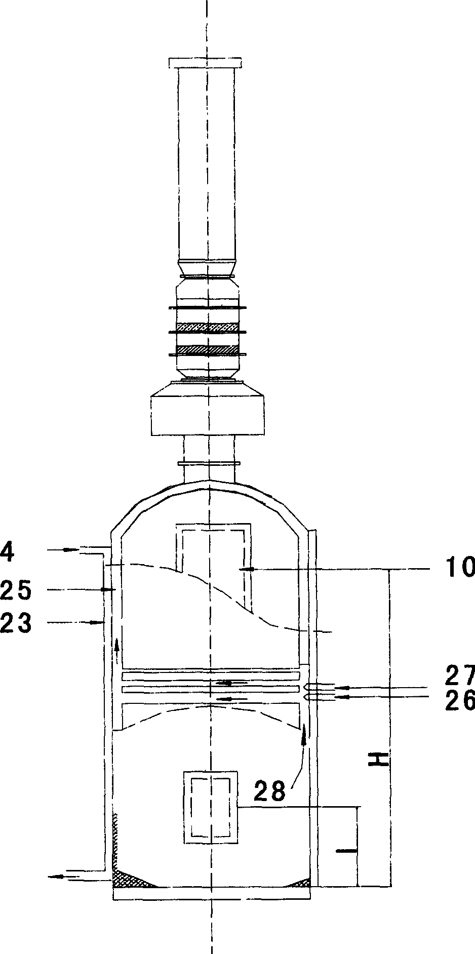
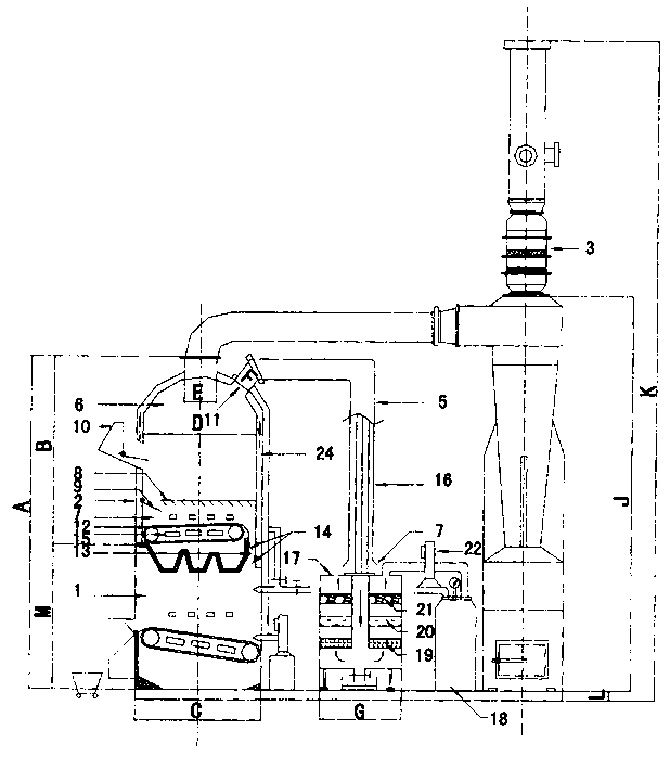
[0009] The overall height of the designed medical waste pyrolysis gasification incinerator body is A (3100mm), and the outer diameter is C (1200mm). It is divided into upper and lower two-layer structure, the lower layer is the incinerator (1) with a height of M (1300mm), the upper layer is the pyrolysis gasifier (2) with a height of B (1800mm), and the outer diameter is D (1000mm). There are water walls. The base height is L (150mm), and the total floor area is 3750×2100m 2 . According to the pyrolysis gasification furnace (2) top 0.5m side is provided with a cracked gas outlet with an opening diameter of F (200mm), the cracked gas outlet is directly connected with the cracked gas-air heat exchanger by the flange, and the cracked gas -The other end of the air heat exchanger is connected to the filter tank (17) whose outer diameter is G (600mm) by a flange. The bottom of the filter tank (17) is provided with a decontamination valve, and the filter tank (17) is provided with...


PUM


Abstract

The incinerator, the gasifying pyrolysis stove as well as the dust removal and fume extractor are utilized in the invented equipment. The incinerator, the pyrolysis gasifying stove and the collector for cracked gas are integrated as whole body. The furnace body of the gasifying pyrolysis oven is divided into a stove chamber and a cracking chamber. The exit of the chain on the bottom of the cracking chamber is connected to the incinerator through a channel. Cracked coke can pass through two windshields in the channel, but fume and frame produced in the incinerator cannot enter into the stove. Thus, gasifying pyrolysis effect is happened in the stove without burning on. Garbage is decomposed into cracked coke, which will be burning in the incinerator, and cracked gas, which will be filteredout. The beneficial effect is that if burning these gases, dioxin will be produced. The combustible gas generated in the stove is as the fuel for the incinerator.

Description

technical field [0001] The invention belongs to garbage incineration treatment equipment. Background technique [0002] In recent years, with the requirements of environmental protection, the development and production of waste incineration devices have been highly valued by many scientific research institutions and enterprises at home and abroad, and their incineration effects, purification efficiency, and automation have been greatly improved, such as rotary incineration. Disposal of complete sets of equipment, pyrophoric incinerators, etc. At present, the working principle of the garbage incinerator is roughly as follows: the garbage is put into the incineration chamber from the material inlet, and at the same time, air and auxiliary high-grade fuel are fed in. Under the condition of sufficient oxygen, the organic matter in the garbage undergoes violent oxidation and exothermic combustion. The characteristic of this type of incinerator is t...

Claims


Application Information

Patent Timeline
IPC IPC(8): F23G5/027
Inventor 李新国汪洪军赵军
Owner TIANJIN UNIV
Why Eureka
Try Eureka