Semiconductor mechanical quantity sensor

A technology of sensors and mechanical quantities, applied in semiconductor devices, semiconductor/solid-state device manufacturing, fluid pressure measurement, etc., can solve problems such as stress attenuation, sensor output changes, etc.

Inactive Publication Date: 2004-01-28
DENSO CORP
View PDF0 Cites 5 Cited by
  • Summary
  • Abstract
  • Description
  • Claims
  • Application Information

AI Technical Summary

Problems solved by technology

Additionally, if such a sensor is actually packaged, at the application temperature, the stress will decay due to the phenomenon of creep
As a result, the output of the sensor will also change due to the creep phenomenon

Method used


Image

  • Semiconductor mechanical quantity sensor
  • Semiconductor mechanical quantity sensor
  • Semiconductor mechanical quantity sensor

Examples


no. 1 example

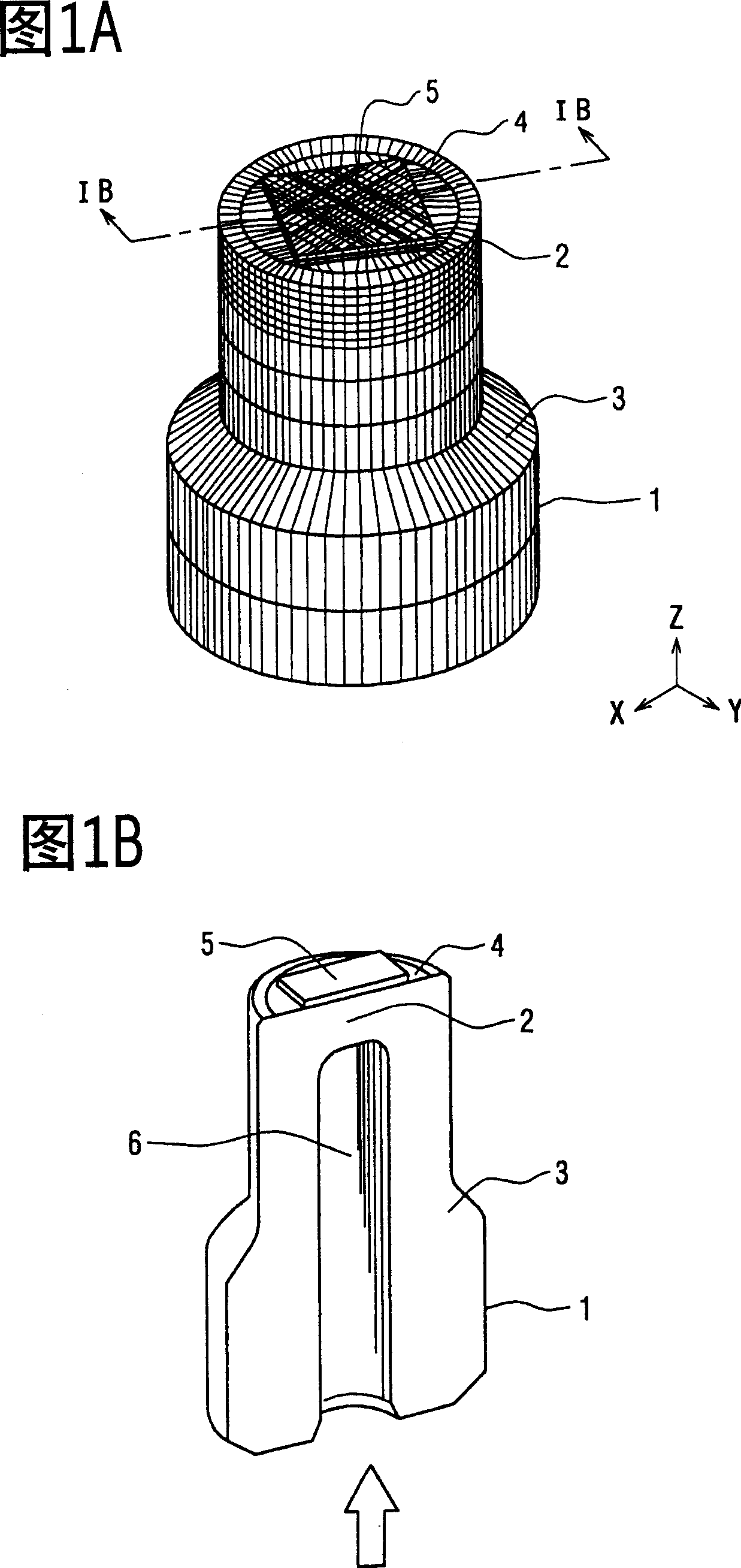
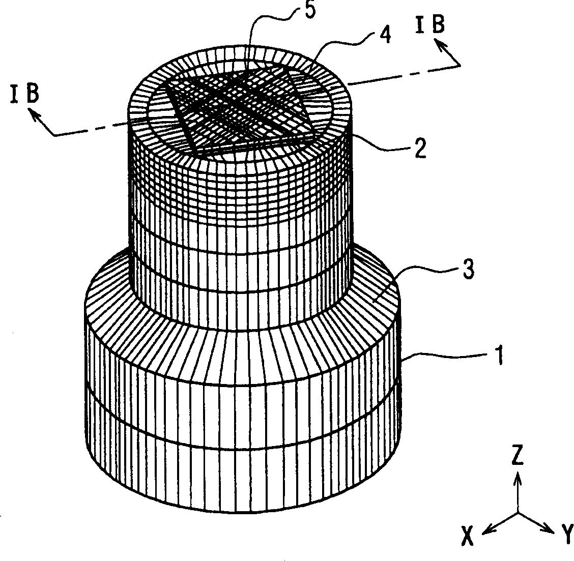
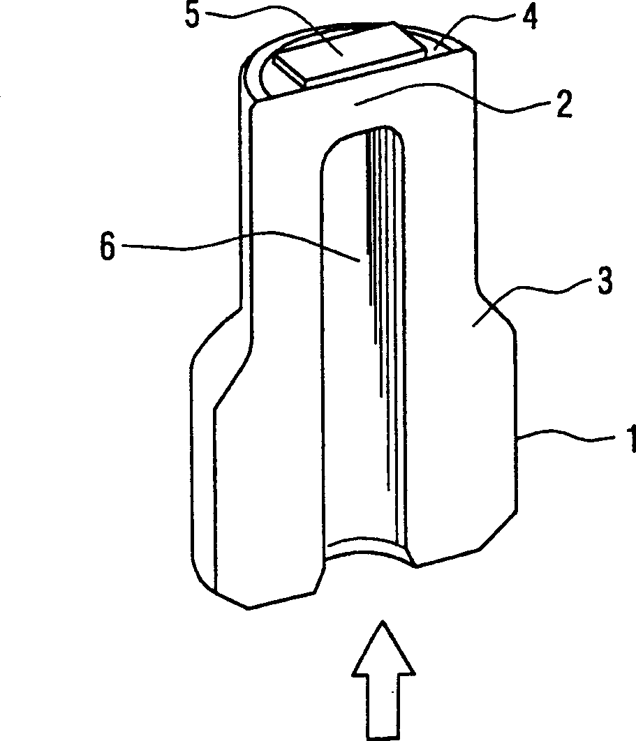
[0015] FIG. 1A is a schematic perspective view of a pressure sensor 1 of an example of the present invention. The pressure sensor 1 as a semiconductor mechanical quantity sensor can be used, for example, to control fuel injection pressure or brake pressure of an engine in a vehicle. The pressure sensor 1 includes a metal rod 3 or a metal step 3 with a disc-shaped metal diaphragm 2 or supporting portion 2 . The pressure sensor 1 also includes an adhesive 4 and a sensor chip 5 . The sensor chip 5 is bonded to the upper surface of the support portion 2 using the adhesive 4 at a predetermined bonding temperature.

[0016] As shown in FIGS. 1A and 1B , the metal rod 3 has a cavity 6 below the upper surface in which the sensor chip 5 is located. A predetermined pressure medium such as a gas and a liquid is introduced into the cavity 6 , and based on the deformation of the bearing 2 and the deformation of the sensor chip 5 , the pressure of the pressure medium is detected.

[0017...


PUM

PropertyMeasurementUnit
deformation rateaaaaaaaaaa

Abstract

A semiconductor dynamic quantity sensor includes a supporting portion, an adhesive, and a sensor chip. The adhesive is located on a surface of the supporting portion. The sensor chip is located on the adhesive. The sensor chip and the supporting portion have been bonded together by heating the adhesive. The adhesive has a deformation factor of 0.5% or smaller at the temperature at which the adhesive is heated for bonding the sensor chip and the supporting portion together in order to reduce the stress caused by the hardening shrinkage of the adhesive.

Description

technical field [0001] The invention relates to a semiconductor mechanical quantity sensor, in particular to an adhesive used for bonding sensor chips. Background technique [0002] When a pressure sensor chip as a semiconductor mechanical quantity sensor is bonded to, for example, a metal diaphragm, a low-melting glass is conventionally used as an adhesive. The low-melting glass is classified as leaded or lead-free according to environmental factors, and in particular, the use of the leaded glass containing lead oxide is controversial in consideration of recent environmental issues. On the other hand, the lead-free glass requires a bonding temperature of, for example, 400 to 500° C. because it is difficult to lower the melting point without adding lead oxide. Therefore, there is a problem that additional thermal energy is required for bonding, or the sensor chip is damaged by the bonding temperature. [0003] Over the years, research has been conducted on bonding sensor c...

Claims


Application Information

Patent Timeline
Patent Type & Authority Applications(China)
IPC IPC(8): G01L9/04G01D5/18G01L9/00H01L21/52H01L29/84
CPCG01L9/0055G01L9/0052
Inventor 田中昌明池泽敏哉斋藤隆重
Owner DENSO CORP
Why Eureka
Try Eureka