
Start of switching reluctance generator

A technology of reluctance and starting winding, which is applied to the starter, motor generator/starter, synchronous generator, etc. of a single synchronous machine, which can solve the problems of hindering the starting system and unable to guarantee the capacity of the capacitor.

Inactive Publication Date: 2004-01-28
NIDEC SR DRIVES
View PDF1 Cites 1 Cited by
  • Summary
  • Abstract
  • Description
  • Claims
  • Application Information

AI Technical Summary

Problems solved by technology

This method is successful if there is sufficient energy remaining in the capacitor at start-up to allow the machine to start properly, at which point there is no guarantee that the capacitor will hold its charge during the extended off-time
In addition, it is often necessary to discharge the capacitor before the maintenance work of the converter, which will also hinder the subsequent start-up of the system in this way.

Method used


Image

  • Start of switching reluctance generator
  • Start of switching reluctance generator
  • Start of switching reluctance generator

Examples


Embodiment Construction

[0041] The Radun article cited above discloses a method of starting a switched reluctance generator, whereby the excitation energy initially comes from a battery, supplying the excitation bus to excite the phase windings of the machine. The generator returns all output to the bus until the bus voltage rises to a suitable value, then closes an additional thyristor switch to send the generator output to the load. Stable operation requires the use of an excitation bus and additional thyristors. A similar system with separate drive and load buses is disclosed in EPA 0564076.

[0042] Unlike prior art systems, the present invention uses a single bus and a separate start winding to boost the DC link capacitor voltage. This is done by introducing an initial flux linkage within the machine, thus producing a DC link voltage sufficient to allow the generator to operate in conventional conditions. This system will be described in detail below.

[0043] Shown in Figure 6 is a cross-sec...


PUM


Abstract

A switched reluctance drive 12' is operated as a generator on a high voltage supply which has no long-term energy storage capability. A low voltage supply 92 is used to start the generator through the use of a dedicated priming winding 65, which provides sufficient energy to allow the generator to build up charge in DC link capacitor(s). Once sufficient charge has built up, the priming winding is de-energised and the generator continues in a steady-state operation.

Description

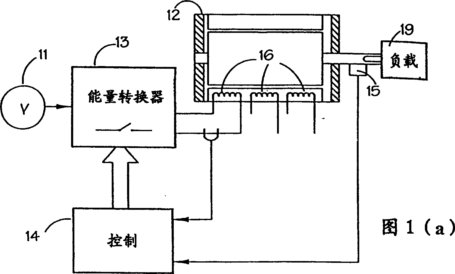
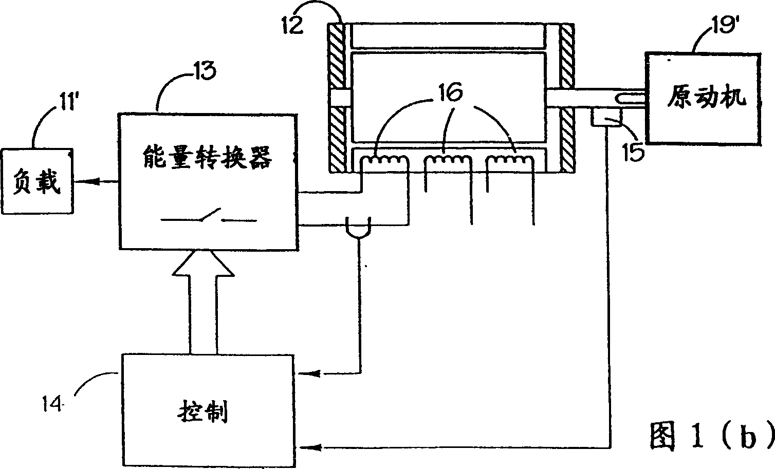
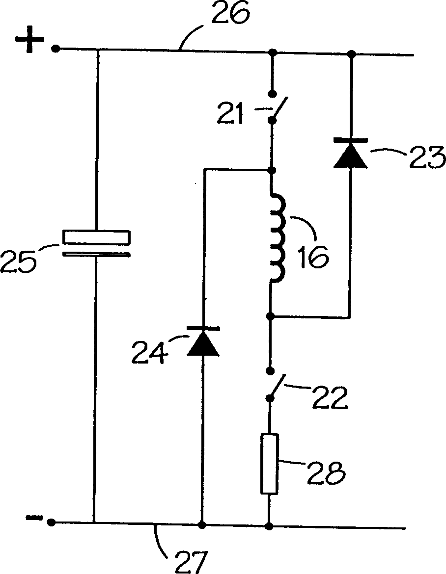
technical field [0001] The present invention generally relates to apparatus and methods for starting power generation systems. More specifically, the present invention relates to the operation of switched reluctance generators for powering power supply systems without long-term energy storage capabilities. Background technique [0002] The characteristics and operation of switched reluctance systems are well known in the art and described, for example, in the article "The characteristics, design and application of switched reluctance motors and drivers" by Stephenson and Blake (PCIM'93, Nurnberg, June 21-24, 1993 Japan), which is hereby incorporated by reference. Figure 1(a) shows a schematic diagram of a typical switched reluctance drive system, here operating as a motor. The switched reluctance machine 12 is connected to a load 19 . The DC power source 11 may be a battery, a shaped and filtered AC power source or other forms of electrical energy storage. The energy con...

Claims


Application Information

Patent Timeline
Patent Type & Authority Applications(China)
IPC IPC(8): H02P25/08H02K19/10H02P1/46H02P9/08H02P9/40
CPCH02P2101/45H02K19/20H02P9/40H02K19/103H02P2009/002H02P1/46
Inventor M·J·特纳
Owner NIDEC SR DRIVES
Learn More