Assembled high-voltage current transformer

A current transformer and high-voltage current technology, which is applied in the direction of inductors, transformers, circuits, etc., can solve the problems of high local field strength, increased cost, and difficult electric field, so as to achieve small impact of stray capacitance, improve product qualification rate, and improve The effect of product quality

Inactive Publication Date: 2004-02-04
ANHUI ITATOM POWER EQUIP
View PDF1 Cites 2 Cited by
  • Summary
  • Abstract
  • Description
  • Claims
  • Application Information

AI Technical Summary

Problems solved by technology

But no matter what kind of current transformer, as the voltage level increases, there will be many problems: usually, every time the voltage level increases by one level, the insulating material will increase a lot, and the square of the voltage level ratio will increase.
The process of wrapping insulation is very complicated, and it can only be wrapped by hand, and insulation defects will inevitably occur, especially the insulation at the triple junction point cannot be as tight as the basic insulation, which becomes a weak link in the insulation structure, and it is easy to break the gap during the test or operation. Discharge or breakdown occurs at the place; due to the irregular cross-section shape of the two intersecting spiral rings, it is difficult to calculate the electric field of the chain insulation, which may cause uneven electric field strength and excessive local field strength, which may damage or damage the product during operation. The design margin is too large, which increases the cost; because all the cores and windings are installed in the porcelain sleeve, its size and weight are relatively large, and this shortcoming is particularly obvious at ultra-high voltage; due to the primary winding and secondary winding of the chain insulation structure The capacitance between the secondary windings is small, and its stray capacitance to the ground is relatively large, so the voltage distribution of the two current transformers is uneven, the upper level is about 55% of the total voltage, and the lower level is 45%, so that the insulation is not sufficient use
Therefore, the above-mentioned cascaded current transformer has not been formed into a commercial product

Method used


Image

  • Assembled high-voltage current transformer
  • Assembled high-voltage current transformer
  • Assembled high-voltage current transformer

Examples


Embodiment Construction

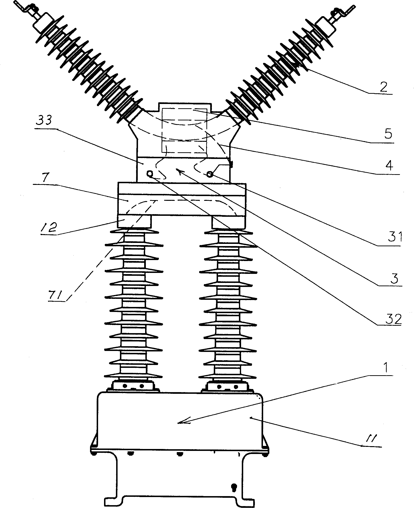
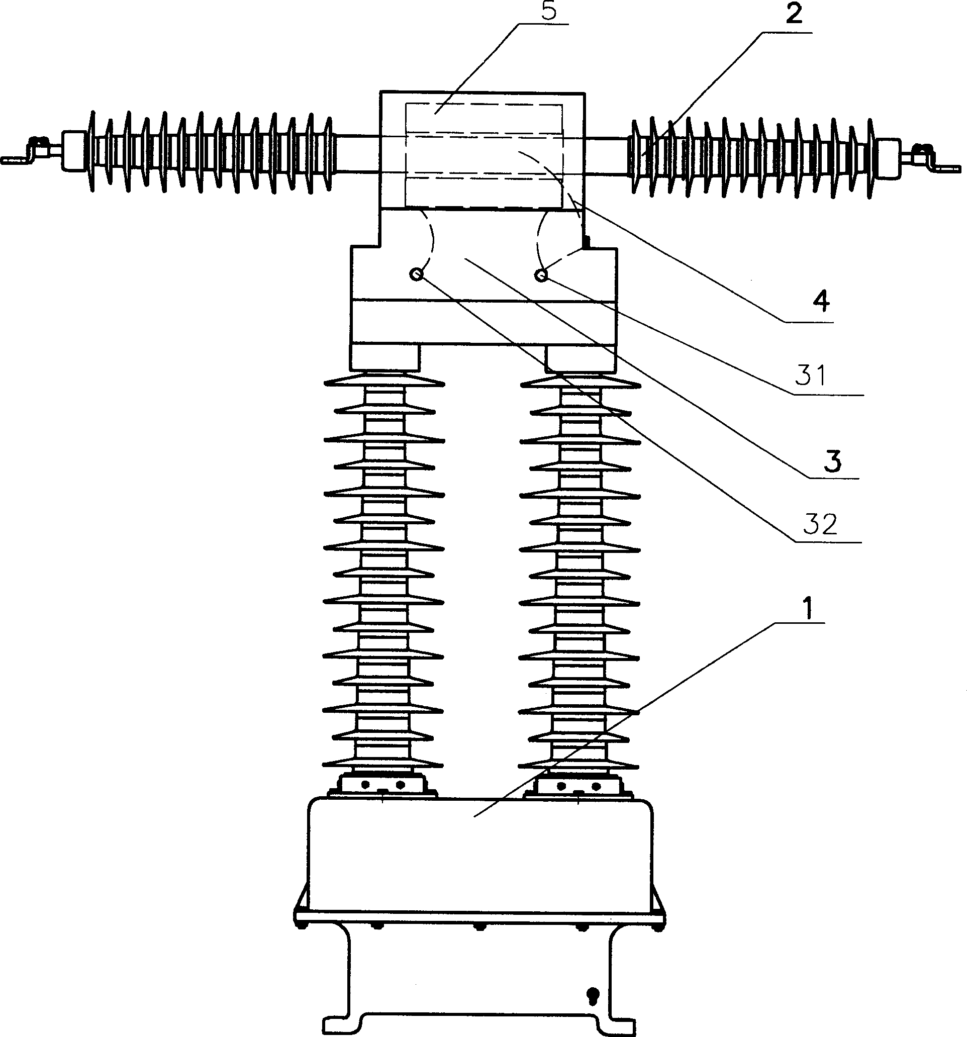
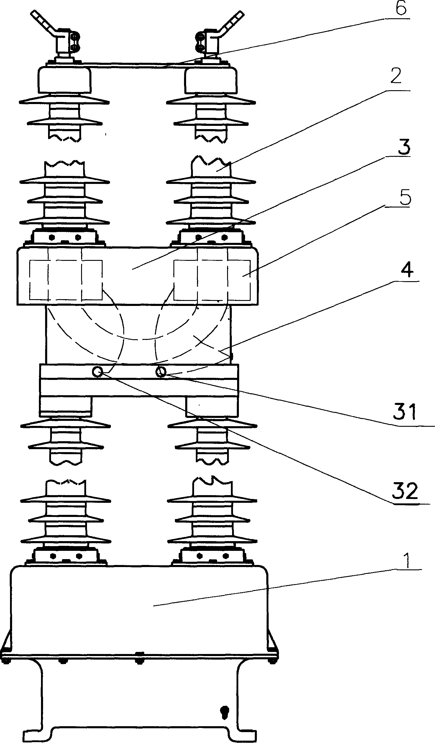
[0011] see figure 1 , which shows the first embodiment of the combined high-voltage current transformer of the present invention. It includes a combination of a capacitive high-voltage bushing 2 on the upper part, a low-voltage through-type current transformer 3 on the middle, and an independent high-voltage current transformer 1 on the lower part.

[0012] The independent high-voltage current transformer 1 is a dry-type high-voltage current transformer, the primary winding adopts a capacitive insulation structure, and has a multi-turn coil wound by mutually insulated wires. Its secondary winding is set according to the needs of users. The part of the primary winding protruding from the base 11 forms double arms extending upward in the vertical direction.

[0013] The capacitive high-voltage bushing 2 is generally V-shaped, and one end of the clamp can be connected to, for example, a substation isolation switch, and the other end of the clamp can be connected to, for example...


PUM


Abstract

In the present invention, the low voltage through type current transformer is firmly assembled outside earthing screen of capacity type high voltage case pipe to form a combination body which is fixed at top of independent high voltage current transofmrer. The tip screen leading wire of high voltage cage pipe is electric-connected to case body of through type current transformer and a coil terminal of it as two coil terminals of it are electric-connected to two primary winding terminals of high voltage. The product of transformation ratio K1 and K2 for above two transformers is equal to transformation ratio K of the combination high voltage current transformer.

Description

Technical field: [0001] The invention relates to a combined high-voltage current transformer, which is used for current measurement and relay protection, and is usually used for voltage levels of 220kV and above. Background technique: [0002] At present, the current transformers of various voltage levels at home and abroad are single-stage current transformers, and most of them are capacitor oil-filled, air-filled or epoxy resin cast current transformers. The ZL99201400.X utility model patent issued by the State Intellectual Property Office on February 2, 2000 discloses a new dry-type high-voltage current transformer proposed by the inventor, which has no leakage, no pollution flashover, fire prevention, explosion protection, Small size, light weight, easy maintenance and other advantages. But no matter what kind of current transformer, as the voltage level rises, many problems will appear: usually, every time the voltage level increases by one level, the insulating materi...

Claims


Application Information

Patent Timeline
Patent Type & Authority Applications(China)
IPC IPC(8): H01F38/28
Inventor 黄维枢
Owner ANHUI ITATOM POWER EQUIP
Why Eureka
Try Eureka