
Method and equipment for detecting single plate by JTAG

A technology of testing equipment and testing methods, which is applied in the direction of detecting faulty computer hardware, etc., can solve the problems of high cost, achieve the effects of avoiding losses, improving the correct rate of diagnosis, and reducing the difficulty of operation

Inactive Publication Date: 2004-02-11
UT STARCOM CHINA
View PDF0 Cites 21 Cited by
  • Summary
  • Abstract
  • Description
  • Claims
  • Application Information

AI Technical Summary

Problems solved by technology

However, at present, chip testing combined with JTAG requires large-scale ICT (In-Circuit Test) equipment or ATE (Automatic Test Equipment) support, and the cost is very high

Method used


Image

  • Method and equipment for detecting single plate by JTAG
  • Method and equipment for detecting single plate by JTAG
  • Method and equipment for detecting single plate by JTAG

Examples


Embodiment Construction

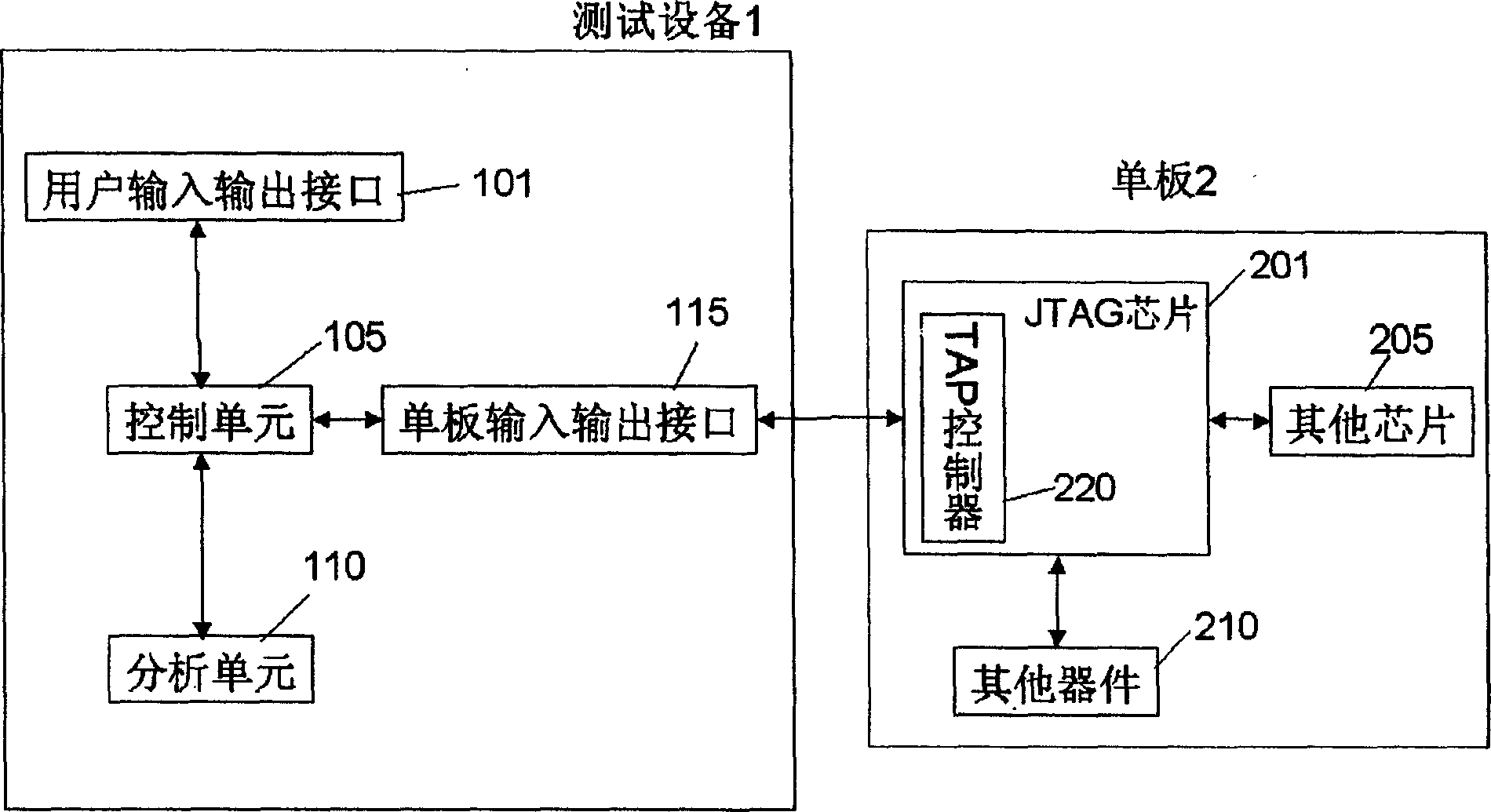
[0012] figure 1 A schematic view of a testing device according to the invention is shown.

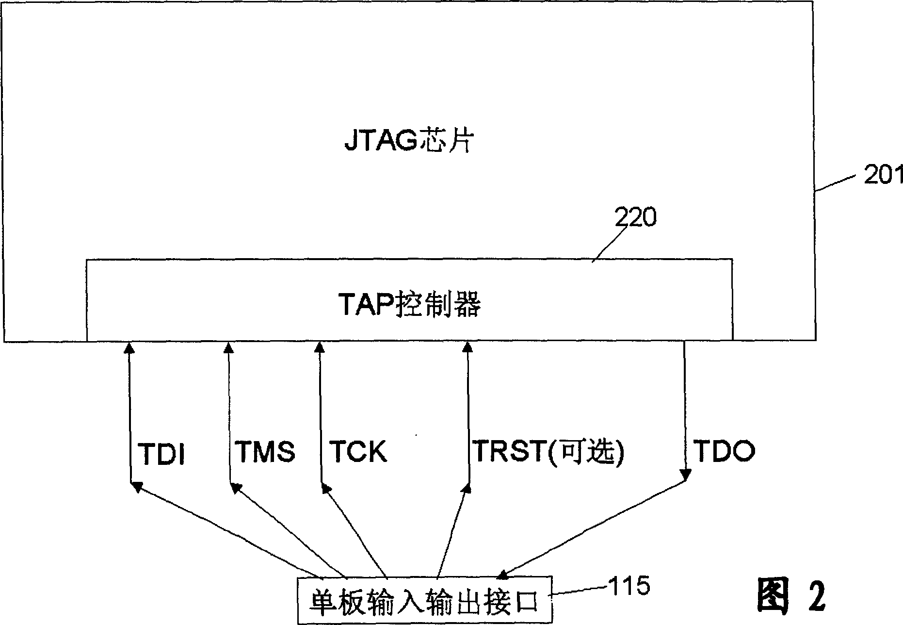
[0013] According to the present invention, in order to test the single board 2, a chip 201 (hereinafter referred to as the JTAG chip) supporting the JTAG function needs to be arranged on the single board 2, and the JTAG chip 201 includes a TAP (Test Access Port) controller 220, and the TAP controls The TAP control signal provided by the device 220 includes:

[0014] TCK: Test Clock test clock (input)

[0015] TDI: Test Data In test data input (input)

[0016] TMS: Test Mode Select test mode selection (input)

[0017] TDO: Test Data Out test data output (output)

[0018] TRST: Test Reset Test reset (input) (optional).

[0019] The above-mentioned TAP control signal is extracted from the TAP controller 220 on the JTAG chip for use by the present invention to test the single board under test.

[0020] Such as figure 1 As shown, in order to test the single board 2 with the JTAG chip ...


PUM


Abstract

The present invention discloses a kind of method and equipment for detecting single plate by means of JTAG. The method includes analyzing BSDL file; displaying or altering chip pin state intuitivelyvia man-computer interface; and judging where the single plate fault is. The said method increases few design cost, raises the correctness of single plate diagnosis, makes operation more easy and avoids the loss caused by unnecessary chip replacement.

Description

technical field [0001] The invention relates to the field of electronic equipment, in particular to a method and equipment for testing a single board through JTAG (Joint Test Action Group). Background technique [0002] During the board commissioning process, it is often necessary to diagnose the board hardware to determine whether the chip is damaged, a PCB (Printed Circuit Board) fault, or a processing fault (short circuit, solder joint, etc.). In the prior art, an oscilloscope is most commonly used to observe the state of the pins of the chip under test. However, there are many defects in this method, such as accidentally short-circuiting the pins connected to the chip to damage the chip, or the chip has a lot of pins, which is difficult to measure, or the chip is packaged with BGA (Ball Grid Array), and the oscilloscope probe cannot be placed on the tube at all. on feet. If you don't know whether the chip is damaged or has a welding problem, you need to replace the chi...

Claims


Application Information

Patent Timeline
IPC IPC(8): G06F11/22
Inventor 魏昊
Owner UT STARCOM CHINA
Features
  • Generate Ideas
  • Intellectual Property
  • Life Sciences
  • Materials
  • Tech Scout
  • Unparalleled Data Quality
  • Higher Quality Content
  • 60% Fewer Hallucinations
Learn More