Monitoring method and device for wave-length-division multiplexing optical signal/noise ratio

A technology of monitoring device and signal-to-noise ratio, which is applied in the direction of wavelength division multiplexing system, selection device, electromagnetic wave transmission system, etc., can solve the problems of small test dynamic range, low price, and not yet mastered, so as to improve the dynamic range and improve The effect of safe operation and easy device

Inactive Publication Date: 2004-02-11
FENGHUO COMM SCI & TECH CO LTD
View PDF0 Cites 7 Cited by
  • Summary
  • Abstract
  • Description
  • Claims
  • Application Information

AI Technical Summary

Problems solved by technology

But it also has the problems of small test dynamic range, low precision, complex technology, and not cheap price, and such technology has not yet been mastered in China.

Method used


Image

  • Monitoring method and device for wave-length-division multiplexing optical signal/noise ratio
  • Monitoring method and device for wave-length-division multiplexing optical signal/noise ratio
  • Monitoring method and device for wave-length-division multiplexing optical signal/noise ratio

Examples


Embodiment Construction

[0064] The following will be described in detail in conjunction with the accompanying drawings and embodiments.

[0065] 1. Monitoring method of wavelength division multiplexing optical signal-to-noise ratio

[0066] There are the following specific steps:

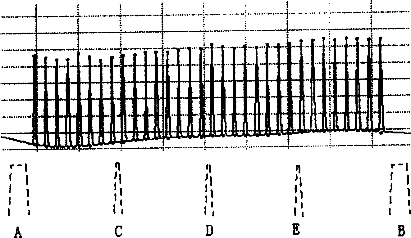
[0067] A. Use a high-precision spectrum analyzer to test the calibration signal (using the actual signal to be tested) to obtain accurate optical signal-to-noise ratio data OSNR N , and enter the microcontroller;

[0068] B. Input the calibration signal into the test device to monitor the optical power P of each optical channel N , the power NP of each noise platform monitoring point M ;

[0069] C. Issue equipment calibration instructions, and the single-chip computer calculates the noise power of each channel: N N =P N -OSNR N ;

[0070] D. According to the center wavelength λ of each channel N , the central wavelength λ of each noise platform monitoring point M , and the monitoring power NP of each noise platf...


PUM


Abstract

This invention discloses optical s/n ratio monitor method of WDM and its device relating to an optical s/n ratio monitor technology of WDM and OADM transmission system. The device has an independent type, a type of wave synthesizer composed of signals, noise separation/noise filter module, WDM channel optical power monitor, photoelectric detecting diode/log amplified circuit, monolithic device and its data collection interface, optical coupler, an optical divider, a OADM and a optical synthesizer. The signal, noise separation/noise filter module in types of front end, rear mount and parallel is composed of a film optical filter plate/fiber grating filter.

Description

technical field [0001] The invention relates to a technique for monitoring the optical signal-to-noise ratio of a wavelength division multiplexing (WDM) and optical add-drop multiplexing (OADM) transmission system; in particular, it relates to a method and a device for monitoring the optical signal-to-noise ratio. Background technique [0002] The so-called WDM transmission system is to use the principle that different optical wavelengths are independent and non-interfering with each other in an optical fiber to transmit multiple signals from different sources to achieve the purpose of expanding the transmission capacity. In order to increase the transmission distance of the equipment and reduce the manufacturing cost of the equipment, a large number of optical fiber amplification technologies are often used in the system. Because optical amplification is an analog processing technology in the optical domain, the digital optical transmission system presents many characterist...

Claims


Application Information

Patent Timeline
Patent Type & Authority Applications(China)
IPC IPC(8): H04B10/077H04B10/079H04J14/02H04Q3/52
Inventor 雷非王红启陈静伟吴珊
Owner FENGHUO COMM SCI & TECH CO LTD
Why Eureka
Try Eureka