Circuit used for eliminating energy saving lamp stroboscopic effect

A stroboscopic effect, energy-saving lamp technology, applied in the field of electric light sources, can solve problems such as restricting applications, and achieve the effects of wide applicability, strict isolation, and expansion of application scope

Inactive Publication Date: 2004-02-18
XINGRONG HARDWARE ELECTRICAL MATERIAL & APPLIANCES SHOP HONGKOU DISTRICT SHANGHAI
View PDF0 Cites 2 Cited by
  • Summary
  • Abstract
  • Description
  • Claims
  • Application Information

AI Technical Summary

Problems solved by technology

This protection circuit has certain limit...

Method used


Image

  • Circuit used for eliminating energy saving lamp stroboscopic effect
  • Circuit used for eliminating energy saving lamp stroboscopic effect
  • Circuit used for eliminating energy saving lamp stroboscopic effect

Examples


Embodiment 1

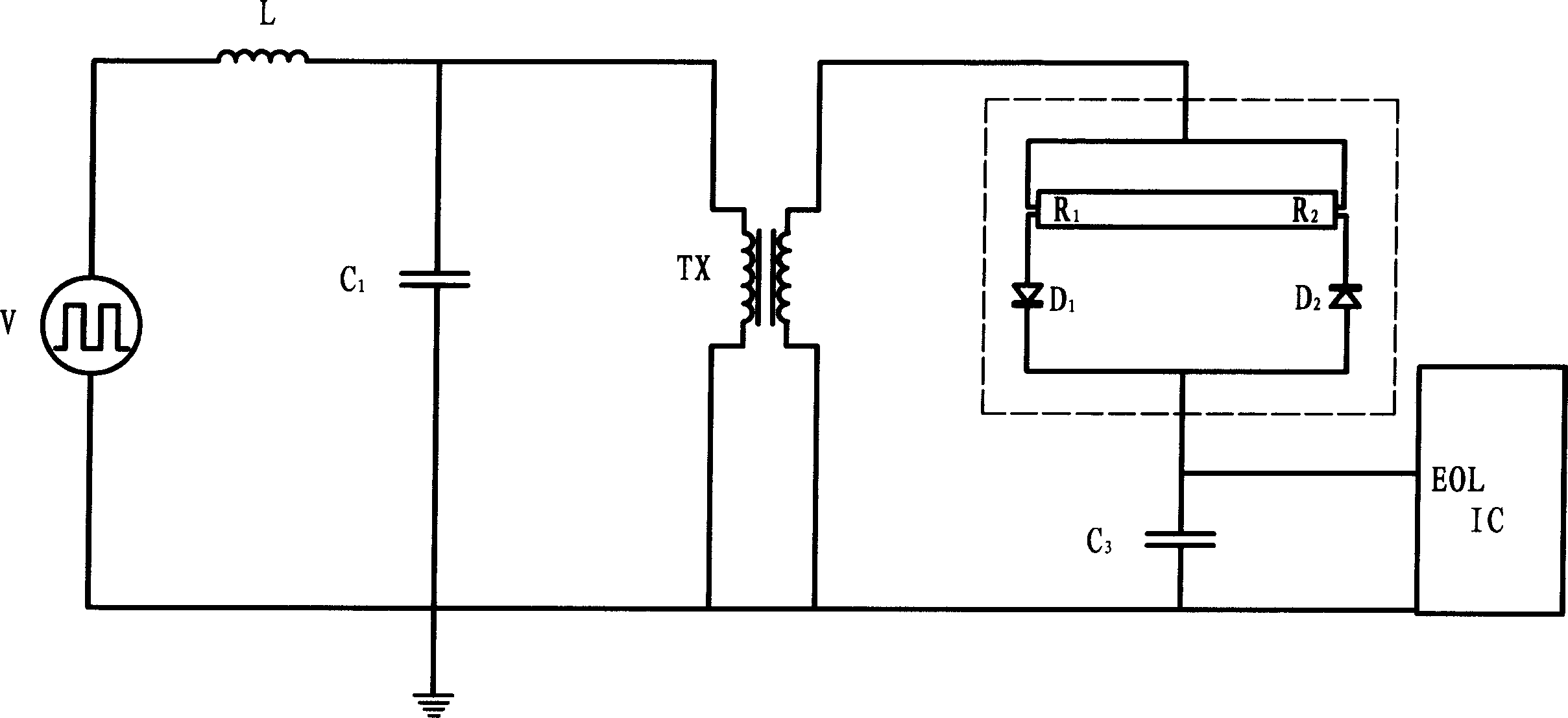
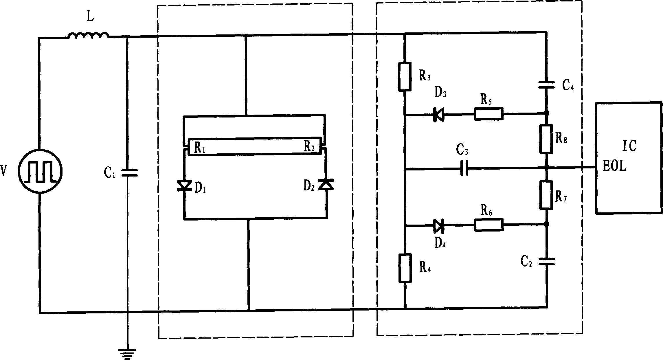
[0010] See attached figure 2 , square wave signal source V, series resonant inductor and capacitor L and C 1 , R 1 , R 2 、D 1 、D 2 expression with figure 1 same. When R 1 and R 2 The resistance values ​​are not equal. The lamp voltage passes through the resistor R 3 , R 4 voltage divider, diode D 4 , resistance R 6 and capacitance C 2 Constitute a half-wave rectifier filter circuit, in the capacitor C 2 The voltage generated on is proportional to the non-inverting peak value of the lamp voltage. Diode D 3 , resistance R 5 and C 4 Constitute another half-wave filter circuit, in the capacitor C 4 The voltage generated on is proportional to the negative phase peak of the lamp voltage. Capacitance C 2 A positive voltage on the R 7 For capacitance C 3 For forward charging, the capacitor C 4 The negative voltage on the resistor R 8 For capacitance C 3 For reverse charging, the capacitor C 3 The voltage signal on it is sent to the control circuit IC. The c...

Embodiment 2

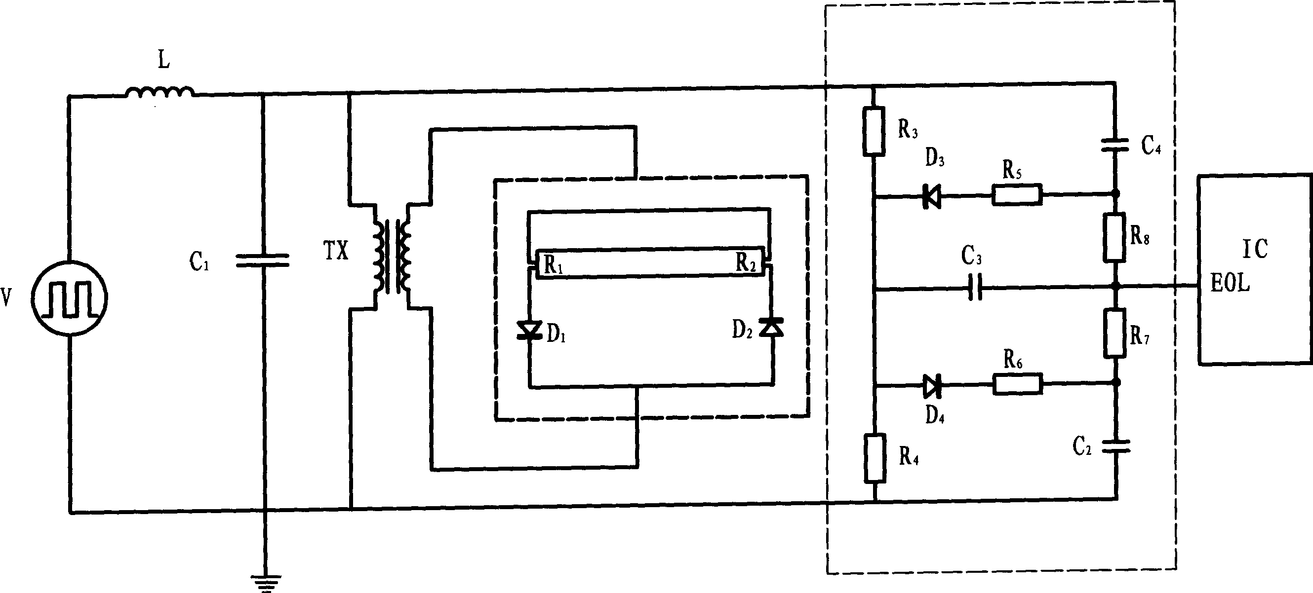
[0012] attached image 3 It is an embodiment where the lamp load is isolated from the electronic rectifier. Resistance R 3 , R 4 , R 5 , R 6 , R 7 , R 8 , capacitance C 2 、C 3 、C 4 , Diode D 3 、D 4 A detection circuit is formed, and the working principle of the circuit is also to judge whether the energy-saving lamp is in the rectification state by detecting the asymmetry of the positive and negative amplitudes of the AC voltage drop of the lamp. Its specific description is the same as the aforementioned circuit.


PUM


Abstract

The present invention finally obtains control circuit for vibration stop by connecting positive and negative peak value sampling circuit connected with electronic rectifier to positive-negative peak value voltage signal addition circuit and connecting the signal addition circuit with obsolute value comparator. The voltage division of AC voltage drop in energy saving lamp is carried out by the control circuit to obtain positive phase peak value and negative phase peak value of lamp tube voltage separately. Whether vibration stop is carried on or not is decided by the control circuit after the positive-negative peak value voltage signals is added and compared.

Description

technical field [0001] The invention relates to an electric light source, in particular to an electronic energy-saving lamp powered by high-frequency alternating current. Background technique [0002] During the use of electronic energy-saving lamps powered by high-frequency AC power in the prior art, as the lamp tube ages, the thermionic emission energy of the filament cathode gradually decreases, and the voltage of the lamp tube increases. However, due to the aging degree of the filament at both ends of the lamp tube, it is impossible Consistent, the electron emission capabilities of the two filament cathodes are different, and the positive and negative parts of the alternating current flowing through the lamp tube are also different, that is, the so-called "rectification effect" is produced, resulting in a significant increase in the filament voltage and a sharp rise in the temperature of the filament electrode. The electronic rectifier fails due to excessive output power...

Claims


Application Information

Patent Timeline
IPC IPC(8): H05B41/298
Inventor 徐有强
Owner XINGRONG HARDWARE ELECTRICAL MATERIAL & APPLIANCES SHOP HONGKOU DISTRICT SHANGHAI
Why Eureka
Try Eureka