Building with solar ultilization system

A solar energy and building technology, applied in the field of solar system buildings, can solve problems such as large temperature differences, and achieve the effect of saving on-site construction

Inactive Publication Date: 2004-03-03
オーエムソーラー協会 +1
View PDF0 Cites 12 Cited by
  • Summary
  • Abstract
  • Description
  • Claims
  • Application Information

AI Technical Summary

Problems solved by technology

[0015] However, this method is limited to the concrete of the interior space in the so

Method used


Image

  • Building with solar ultilization system
  • Building with solar ultilization system
  • Building with solar ultilization system

Examples


Embodiment Construction

[0060] The embodiments of the present invention will be described in detail below with figures.

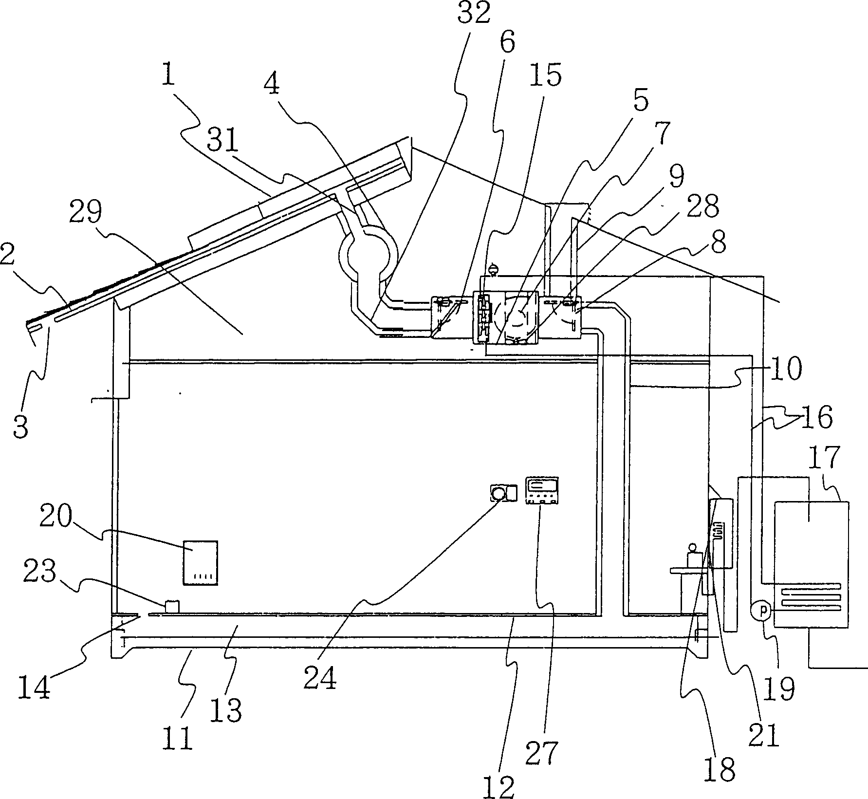
[0061] figure 1 The solar system building according to the invention is shown with a sloping roof. The roof is used as the heat collecting part of the solar heat, and the air channel 2 with the roof slope is formed under the heatable roof board 1 made of metal materials such as colored iron plates or tiles and other materials. The lower side of the air passage 2 is shielded with a heat insulating plate. In addition, one end of the air passage 2 is provided with an air inlet 3 at the eaves or the like. The other end of the air passage 2 is located at a higher part of the roof and serves as an air outlet 31 . The outflow port is connected with the channel 32 and communicates with the girder channel 4 as a heat collecting channel.

[0062] The girder channel 4 is made of heat-insulating material, and it can be designed indoors, such as being arranged in a small house interior 29...


PUM


Abstract

A building with a solar system for supplying heat or cold, exchanging air, removing moisture, and supplying hot water is composed of a solar heat collecting unit close to the metallic roof and with slope air channel, a treating box with check valve, switching valve between flowing down channel and exhaust channel, and heat-collecting fan installed between said check valve and switching valve, and the connecting pipelines for connecting solar heat collector with indoor heat collecting chamel, treating box and the flowing down and exhaust channels in turn. Its advantage is optimal use of solarenergy.

Description

technical field [0001] The present invention relates to a solar system building that uses solar energy to heat air for heating and the like. Background technique [0002] The increase in carbon dioxide produced by human activities has threatened the earth's environment itself. Most of the reasons are caused by the developed countries who agree with the energy consumption type civilization. [0003] If most developing countries also pursue the ideal model of developed countries, the earth's environment will definitely be further damaged. [0004] However, this does not require people in developing countries to give up the "richness" enjoyed by developed countries. [0005] Mass consumption of resources should by no means be a privilege accorded only to developed countries. [0006] Now, what the developed countries should do is not to lower the standard of living, but to figure out how to reduce the environmental load while improving the standard of living. [0007] There...

Claims


Application Information

Patent Timeline
IPC IPC(8): E04D13/18F24F5/00F24F13/06
CPCY02B10/20Y02B10/24Y02A30/272
Inventor 武山伦
Owner オーエムソーラー協会
Why Eureka
Try Eureka