

Water coke slurry buring technology
A combustion technology, water coke slurry technology, applied in the field of water coke slurry combustion, can solve problems such as difficulties in the ignition and stable combustion process of water coke slurry
- Summary
- Abstract
- Description
- Claims
- Application Information
AI Technical Summary
Problems solved by technology
Method used
Image

Examples
Embodiment Construction
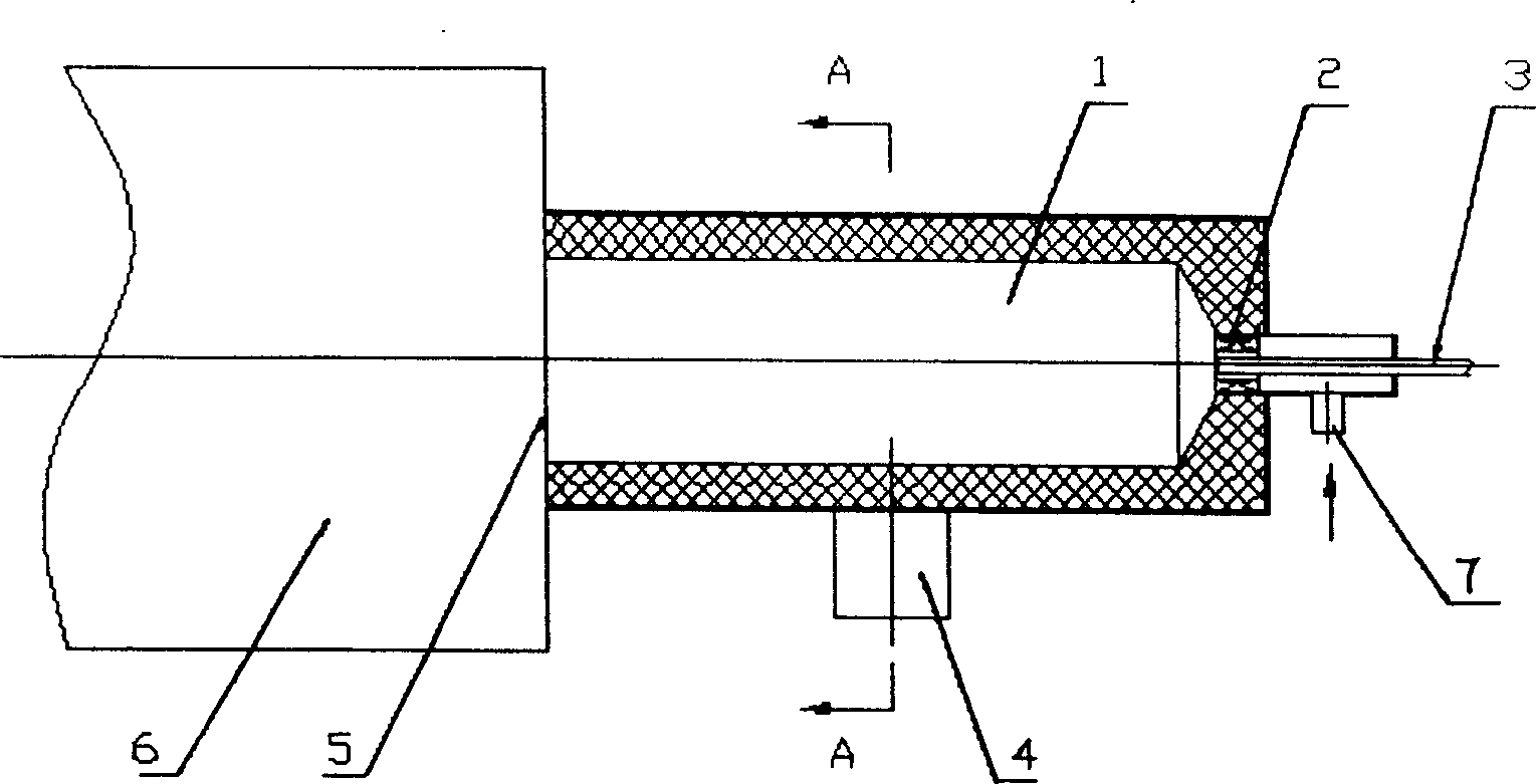
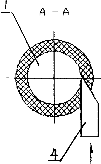
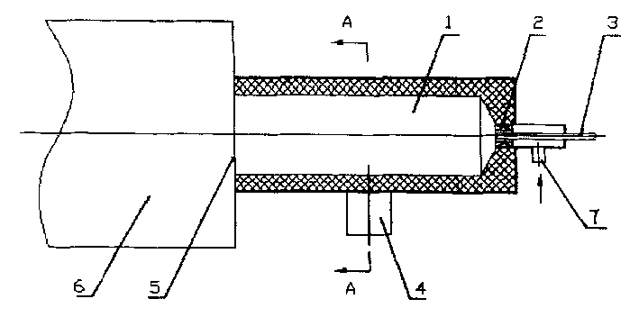
[0011] figure 1 Middle: 1. Pre-combustion chamber 2. Swirl burner 3. Atomizing spray gun 4. Tangential air inlet 5. Open mouth 6. Industrial furnace 7. Air inlet
[0012] One end of the pre-combustion chamber 1 is connected to the primary air swirl burner 2, and the air inlet 7 is located at the bottom of the swirl burner 2. The primary air enters the air inlet 7 and rotates into the pre-combustion chamber 1 through the swirl burner 2. The swirling intensity is greater than 3.0, the secondary air enters from the tangential air inlet 4 near the middle area of the pre-combustion chamber 1, the tangential secondary air velocity is 25-40m / s, and the atomizing spray gun 3 is placed in the center of the swirling burner 2. In the area, the other end of the pre-combustion chamber 1 is an open port 5 connected to an industrial kiln 7. In the initial stage, the oil is burned first. When the temperature in the pre-combustion chamber 1 reaches at least 950~1000℃, the water coke slurry is ...
PUM
 Abstract
Description
Claims
Application Information