Coating drying solidifying forced convection heating furnace with suspending conveying workpiece device

A technology of forced convection and heating furnace, which is applied in the direction of heating devices, progressive dryers, lighting and heating equipment, etc., which can solve the problem of serious flow heat loss and achieve the effect of saving heating energy

Inactive Publication Date: 2004-03-03
曹义东
View PDF1 Cites 7 Cited by
  • Summary
  • Abstract
  • Description
  • Claims
  • Application Information

AI Technical Summary

Problems solved by technology

[0003] The Chinese patent application number 97212288 discloses a high-infrared continuous radiation furnace. The workpiece conveying device is installed above the heating furnace. The two ends and the entire top of the heating furnace are completely open. The heating furnace is equipped with high-density Electric heating infrared radiation element, although the conveying device of this kind of heating furnace does not heat together with the workpiece, but because the two ends and the furnace top are open, the natural convection heat loss is very serious, and only radiation heating can be used

Method used


Image

  • Coating drying solidifying forced convection heating furnace with suspending conveying workpiece device
  • Coating drying solidifying forced convection heating furnace with suspending conveying workpiece device
  • Coating drying solidifying forced convection heating furnace with suspending conveying workpiece device

Examples


Embodiment 1

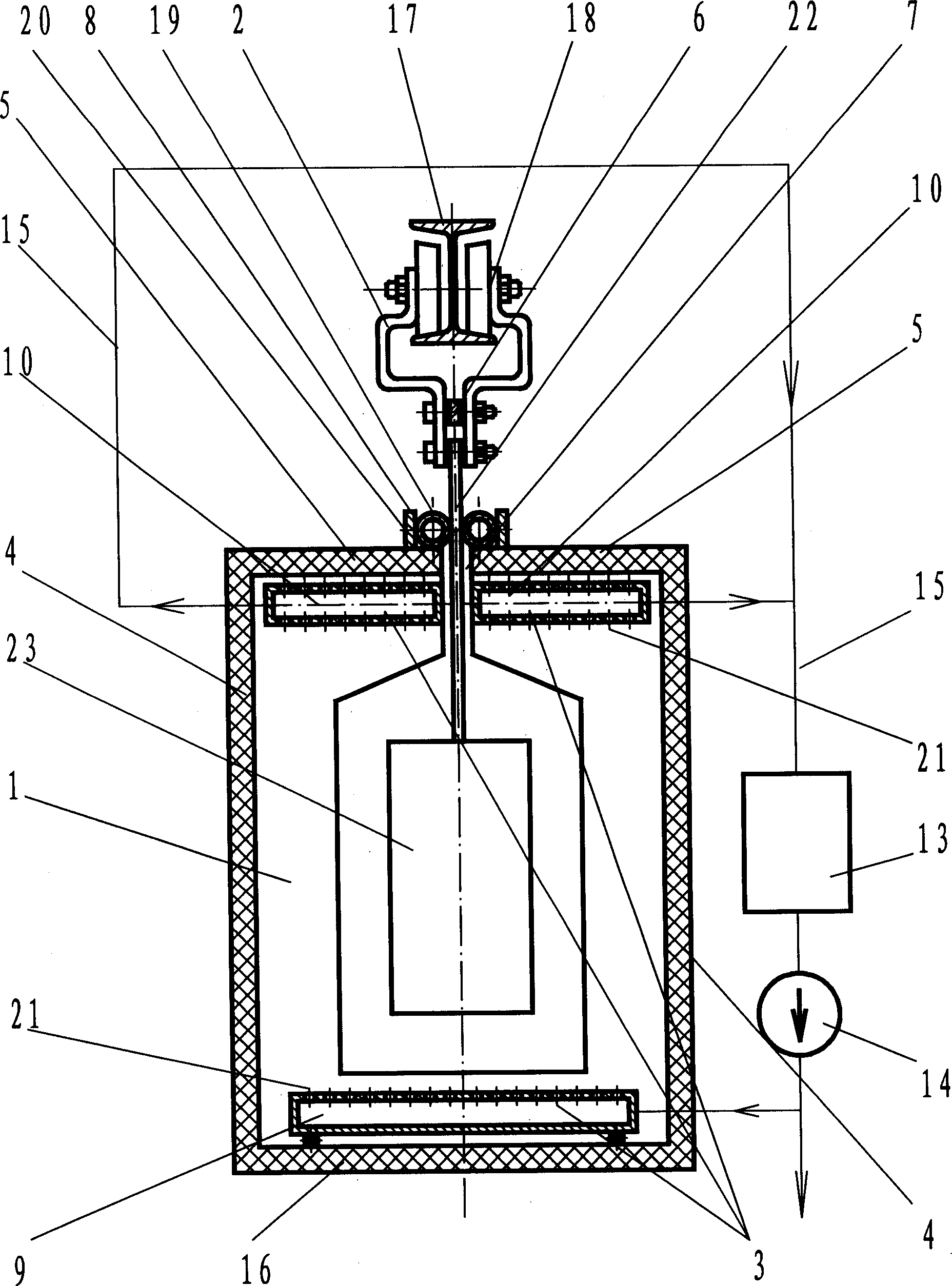
[0020] as attached figure 1 As shown, this embodiment mainly includes a heating furnace 1, a suspension conveying device 2, a forced convection device 3 in the furnace, a hot blast stove 13, a circulating fan 14, a circulating air duct 15, and an opening seam shielding device 8. The heating furnace is surrounded by the furnace side wall 4, the furnace bottom 16 and the furnace roof wall 5. There is a longitudinal continuous opening 7 in the center of the furnace roof 5. The width of the continuous opening 7 is 30 mm; the opening slit shielding device 8 is provided On the outside of the furnace roof wall, on both sides of the continuous opening slit 7, it mainly includes the canvas tube 19 positioned at both sides of the opening slit 7 and the limit baffle 20 fixed on the outside of the canvas tube 19, the canvas tube is filled with water, and the canvas tube The diameter is 100mm, and the distance between the opposite surfaces of the two limit baffles is 190mm; the forced conv...

Embodiment 2

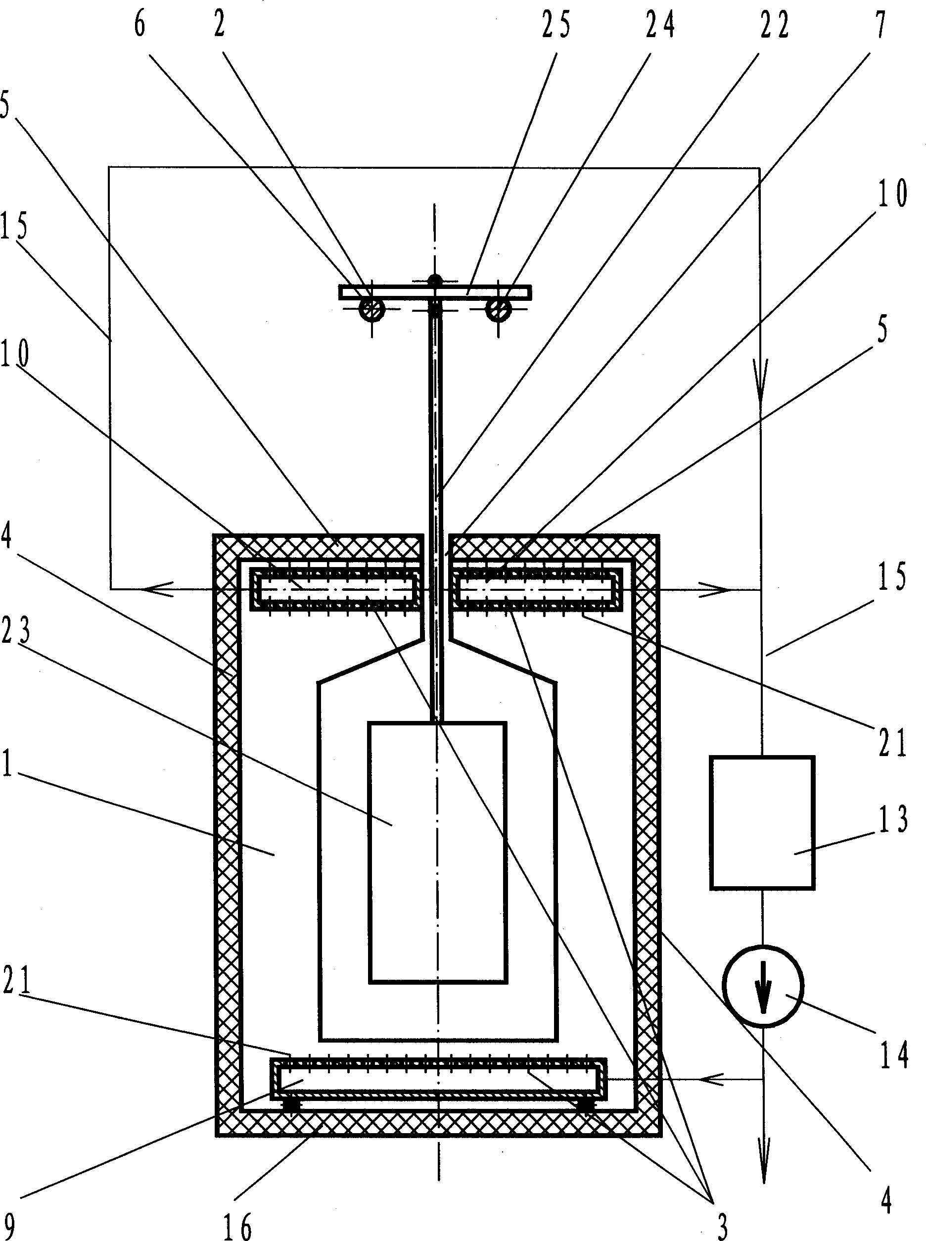
[0022] as attached figure 2 As shown, this embodiment is basically the same as Embodiment 1, with two points of difference: the first point is that there is no opening seam shielding device; Bars are on the same horizontal plane and parallel steel wire ropes 24 and cross bars 25 fixed on the two steel wire ropes 24. The cross bar 25 is perpendicular to the steel wire ropes 24, and a cross bar 25 is fixed every certain distance along the length direction of the steel wire ropes.

Embodiment 3

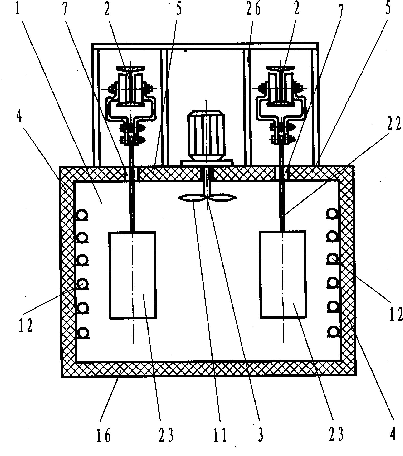
[0024] as attached image 3 , attached Figure 4 As shown, this embodiment mainly includes a heating furnace 1, a suspension conveying device 2 and a forced convection device 3 in the furnace; Located at the same end; the heating furnace is surrounded by the furnace side wall 4, the furnace bottom 16 and the furnace roof wall 5. There is a "U"-shaped continuous opening 7 in the center of the furnace roof 5. The width of the continuous opening 7 is 25mm and parallel to the conveying track in the suspension conveying device, the furnace roof wall in the middle part is completely suspended and fixed by the support 26; the forced convection device 3 in the heating furnace is mainly several forced convection fans 11 located above the furnace; A number of regularly distributed electric heating tubes 12 are arranged on the inner surface of the furnace side wall 4 .


PUM


Abstract

A heating furnace with forced convection for drying and solidifying the coated workpieces which are hung and delivered is composed of the heating furnace consisting of forced convection unit, side walls and top wall, and the hanging-delivering apparatus with delivering chain which can pass through the slit on top wall of heating furnace. Its advantage is high utilization rate of heat energy.

Description

(1) Technical field [0001] The invention belongs to the technical field of coating drying and curing heating, in particular to a coating drying and curing forced convection heating furnace for hanging and conveying workpieces, in particular to an energy-saving coating drying and curing forced convection heating furnace for hanging and conveying workpieces. (2) Background technology [0002] Most of the coatings need to be heated in a heating furnace after being applied to the workpiece to make the coating dry, level and cure, and the coating drying and curing heating furnace installed on the coating line is generally For hanging conveying workpieces, the hanging conveying device is generally installed in the heating furnace. The painted workpieces are hung on the conveying carriage through hangers, and are heated while traveling along the conveying track driven by the conveying chain. Since the conveying carriage and the conveying chain are heated together with the workpiece...

Claims


Application Information

Patent Timeline
Patent Type & Authority Applications(China)
IPC IPC(8): F26B15/18F26B23/10
Inventor 曹义东吴燕周兰英
Owner 曹义东
Why Eureka
Try Eureka