Equipment for compensating wattless power of electric arc furnace

A technology of power compensation and power compensator, applied in the field of reactive power compensation device of electric arc furnace, can solve the problems of high cost, difficult to implement, small compensation effect, etc., and achieve the effect of improving economic benefits

Inactive Publication Date: 2004-03-10
陈君诚
View PDF0 Cites 9 Cited by
  • Summary
  • Abstract
  • Description
  • Claims
  • Application Information

AI Technical Summary

Problems solved by technology

The reactive power compensator can be self-saturated reactance type SVC, thyristor phase-controlled reactance type (TCR) SVC, thyristor group switching capacitor group type (TSC) SVC, etc. The main disadvantage is that SVC can compensate the upstream reactance of the high voltage side of the electric arc furnace transformer. , to maintain the voltage of the high-voltage side bus bar of the electric arc furnace transformer basically unchanged, the compensation effect is not great, and the cost is high, so it is difficult to implement in practice

Method used


Image

  • Equipment for compensating wattless power of electric arc furnace
  • Equipment for compensating wattless power of electric arc furnace
  • Equipment for compensating wattless power of electric arc furnace

Examples


Embodiment 1

[0022] Embodiment 1. Reactive power compensation device for electric arc furnace

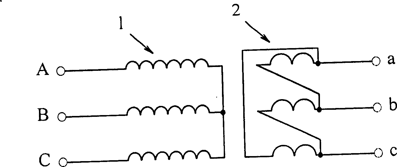
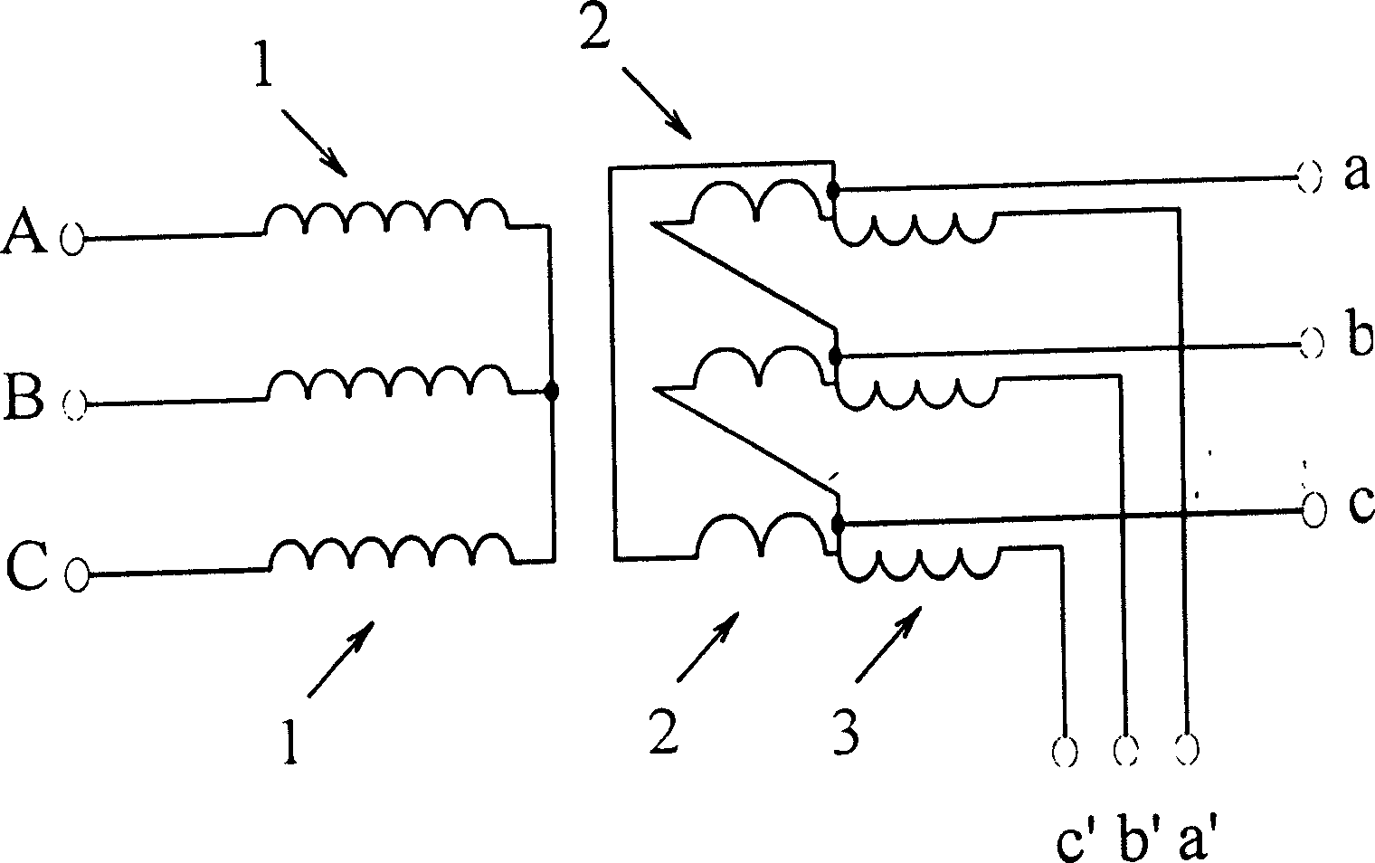
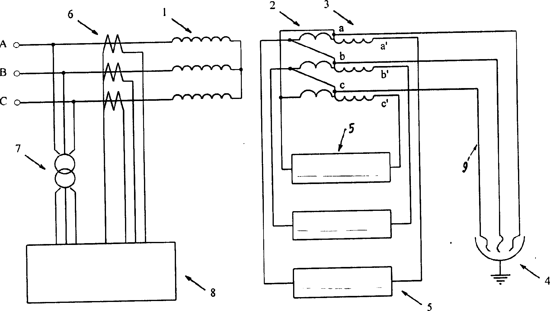
[0023] The electric arc furnace reactive power compensation device of this example, its specific structure is given by image 3 Shown in this example is a phase reactive power compensation device for an electric arc furnace 4, the device includes a transformer high voltage side primary winding 1, a low voltage side secondary winding 2, an electric arc furnace reactive power compensator 5, The current transformer 6, the voltage transformer 7 and the reactive power measuring and controlling device 8, especially including the secondary autocoupling winding 3 on the low-voltage side of the electric arc furnace transformer, are jointly connected and assembled. The secondary auto-coupling winding 3 on the low-voltage side of the electric arc furnace transformer is composed of longitudinally added partial windings on the primary secondary winding 2 on the low-voltage side of the electric arc furnace tr...

Embodiment 2

[0024] The electric arc furnace reactive power compensation device of this example, its specific structure is given by Figure 4It shows that the reactive power compensator 5 on the 4 phases of the electric arc furnace in this example can be connected in a Δ type, and the three terminals of Δ are respectively connected to the outlet terminals a' and b of the secondary autocoupling winding 3 on the low voltage side of the electric arc furnace transformer ', c' on. All the other undescribed are the same as those described in Embodiment 1, and will not be repeated

Embodiment 3

[0025] Embodiment 3. Reactive power compensation device for electric arc furnace

[0026] The specific structure of the reactive power compensation device of the electric arc furnace in this example is shown in Figure 5, and the reactive power compensator 5 on the 4 phases of the electric arc furnace in this example can be connected as a Y 0 Type, Y 0 The three terminals of the electric arc furnace transformer are respectively connected to the outlet terminals a', b' and c' of the secondary autocoupling winding 3 on the low voltage side of the electric arc furnace transformer, Y 0 The zero point is grounded. The rest are the same as those described in Embodiment 1 and Embodiment 2, and will not be repeated here.


PUM


Abstract

The equipment includes primary winding, secondary winding of transformer, reactive power componsator of electric arc furnace, current transformer, potential transformer and test controller for reactive power, and especially, the secondary self coupled winding. The secondary self-coupled winding formed by adding part of winding to original winding at secondary side of transformer of electric arc furnace provides suitable operational voltage and current for reactive power componsator. The componsator connected to ends of coil out a', b', c' can compensate reactive power consumption of furnace as well as zero load reactive loss Qo and short circuit reactive loss Qk in operation of transformer. Thus, voltage of ends of coil out at low voltage side of transformer is stable. The equipment is a feasible reactive power compensator.

Description

1. Technical field [0001] The electric arc furnace reactive power compensation device disclosed by the invention belongs to the technical field of electric power equipment. The device is a practical electric arc furnace non-electrical arc furnace capable of compensating the short-circuit reactance and system reactance of the electric arc furnace transformer and maintaining the voltage at the outlet end of the low-voltage side of the electric arc furnace transformer basically unchanged. Work power compensation device. 2. Background technology [0002] According to the capacity of the electric arc furnace transformer, the high-voltage side voltage is usually 10.5KV, 35KV, 110KV, 220KV, etc., and the low-voltage side voltage is usually in the range of 40V to 800V. The voltage on the high-voltage side and low-voltage side of the electric arc furnace transformer is almost proportional to the capacity of the electric arc furnace transformer. For reactive power compensation of the...

Claims


Application Information

Patent Timeline
Patent Type & Authority Applications(China)
IPC IPC(8): H02J3/18H05B7/144
CPCY02E40/30Y02P10/25
Inventor 陈君诚
Owner 陈君诚
Why Eureka
Try Eureka