

Steel billet feeding cylinder and the method of making and repairing it
A technology of rollers and steel billets, which is applied in the field of conveying devices, can solve the problems of low service life of conveying rollers, and achieve the effects of good red hardness, not easy to wear, and long service life
- Summary
- Abstract
- Description
- Claims
- Application Information
AI Technical Summary
Problems solved by technology
Method used
Image

Examples
Embodiment Construction
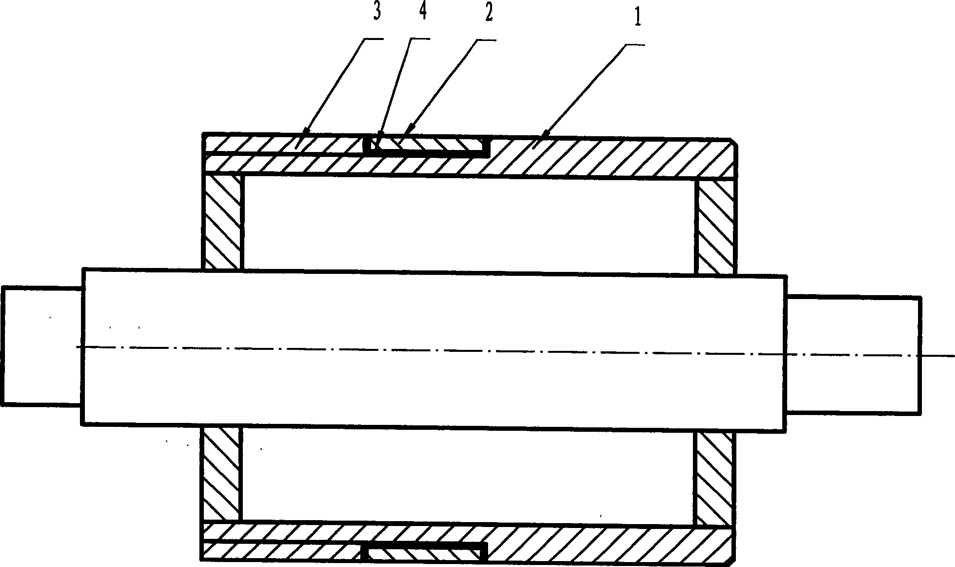
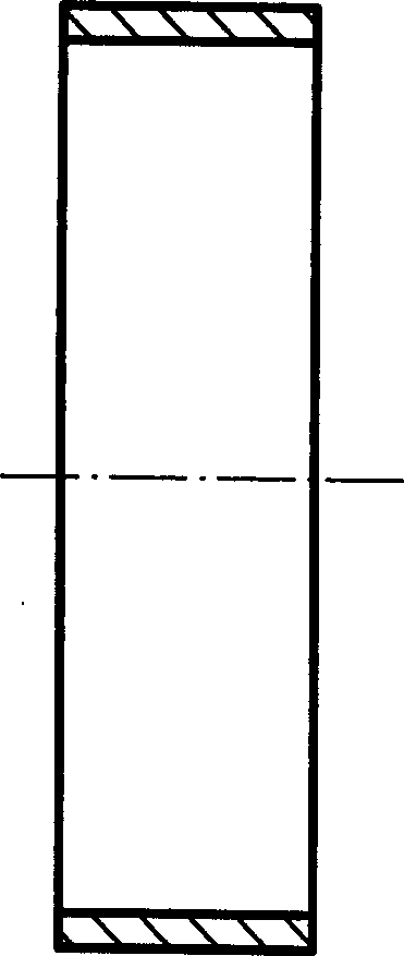
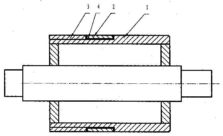
[0014] Such as Figure 1 to Figure 2 As shown, a roller for conveying steel billets is composed of a tungsten carbide roll ring 2 with holes and a base body 1. There is a solder 4 between the tungsten carbide roll ring 2 and the base body 1, and the tungsten carbide roll ring 2 is brazed to the base body 1. Above, the substrate 1 is made of cast steel, the unilateral thickness of the tungsten carbide roller ring 2 is 5 mm, the single-sided gap between the substrate 1 and the tungsten carbide roller ring 2 is 0.2 mm, and the roughness of the joint between the substrate 1 and the tungsten carbide roller ring 2 is ▽5. The main components of the tungsten carbide roll ring 2 are WC80% and Co20%. The hardness of the tungsten carbide roll ring 2 is HRA84.
[0015] A method for manufacturing and repairing a roller for conveying billets, brazing a tungsten carbide roller ring 2 on a substrate 1, the method is as follows:
[0016] 1) Cut 10mm in the diameter of the base body 1;
[00...
PUM
| Property | Measurement | Unit |
|---|---|---|
| thickness | aaaaa | aaaaa |
Abstract
Description
Claims
Application Information