Electric dewatering and desalting appliance for crude oil

A technology of electric desalination and dehydration, crude oil, applied in the direction of electric/magnetic dehydration/emulsification, electric liquid separation, etc., can solve the problem of reducing the efficiency of oil-water separation, retarding the settlement of crude oil, and uneven radial distribution of the electric field intensity of the ring electric field, etc. problems, to achieve the effect of improving the dehydration efficiency of electric desalination, coalescence effect and sedimentation separation speed

Inactive Publication Date: 2004-03-17
CHINA PETROCHEMICAL CORP +1
View PDF3 Cites 18 Cited by
  • Summary
  • Abstract
  • Description
  • Claims
  • Application Information

AI Technical Summary

Problems solved by technology

[0007] The present invention is mainly used to simultaneously solve the following technical problems in the various existing crude oil electric desalination and dehydration devices: the oil-water mixture sequentially passes through the weak electric field region, the transition electric field region and the strong electric field region to make the electric coalescence of the strong electric field region The effect is weakened, which affects and reduces the efficiency of electric desalination and dehydration of crude oil; the crude oil in the tank of the electric desalination dehydrator flows from bottom to top, thereby retarding the settlement of water droplets in crude oil and reducing the efficiency of oil-water separation; using a strong electric field to directly feed multi-stage Electric desalination and dehydration equipment, there are back-mixing of oil-water mixtures with different salt and water contents between the electric fields at all levels; electric desalination and dehydration devices using squirrel-cage electrode assemblies or electrode assemblies with multi-layer electrodes with circular cross-sections, The radial distribution of the electric field intensity of the formed circular electric field is uneven, which affects the effect of electric desalination and dehydration of crude oil, and the power consumption is high

Method used


Image

  • Electric dewatering and desalting appliance for crude oil
  • Electric dewatering and desalting appliance for crude oil
  • Electric dewatering and desalting appliance for crude oil

Examples


Embodiment Construction

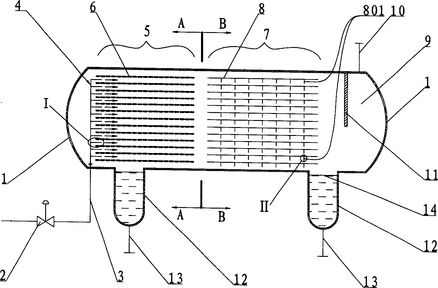
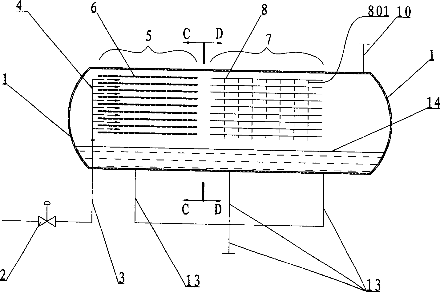
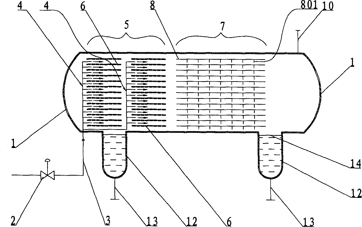
[0040] Such as figure 1 Shown is a kind of crude oil electric desalination dehydrator of the present invention. It includes a horizontal cylindrical tank body 1, one end of the tank body 1 is the inlet port of the oil-water mixture (hereinafter referred to as the inlet port), and the other end is the outlet port of purified crude oil (hereinafter referred to as the outlet port). The bottom of the tank body 1 is provided with two water bags 12, and the bottoms of the water bags 12 are respectively provided with outlet pipes 13. Inside the tank body 1, a feed distributor 4, a strong electric field coalescence zone 5 and a sedimentation separation zone 7 are sequentially arranged along the axial direction of the tank body 1 from the inlet end, and an oil outlet pipe 10 is arranged on the top of the outlet end of the tank body 1. The outlet end of the tank body 1 is also provided with a baffle plate 11 and an oil collection chamber 9 .

[0041] The strong electric field coalesci...


PUM

PropertyMeasurementUnit
water contentaaaaaaaaaa
strengthaaaaaaaaaa
strengthaaaaaaaaaa

Abstract

The electrical raw oil desalting and dewatering device for petrochemical industry features its direct material feeding in strong electric field and horizontal flow of raw oil. The electrical raw oildesalting and dewatering device of the present invention has material distributor and strong electric field coalescence area in tank axial direction and oil outlet pipe in the top of the raw oil purifying area, with the strong electric field coalescence area being provided with at least two layers of parallel electrode plates parallel to or perpendicular to the tank axis. The material distributor is provided with nozzles to spray mixed oil-water material into the strong electric field between two adjacent electrode plates. Between the strong electric field coalescence area and the purified raw oil outlet, deposit separating area may be set.

Description

technical field [0001] The invention relates to a crude oil electric desalination and dehydration equipment used in the petrochemical industry. Background technique [0002] Chinese patent CN2159833Y discloses a squirrel-cage electrode assembly and an electric desalination and dehydration device and process for horizontal flow of crude oil. The oil-water mixture enters the tank from the oil-water mixture inlet of the electric desalination dehydrator tank, flows horizontally through the distribution plate, and passes through the weak electric field area, transitional electric field area and strong electric field area in sequence. The coalesced water droplets settle to the bottom of the tank in a parabolic trajectory, and the desalted and dehydrated crude oil is drawn out from the oil collecting pipe located at the outlet of the purified crude oil in the electric desalting dehydrator tank. This electric desalination dehydrator uses a single-layer electrode, which can be used ...

Claims


Application Information

Patent Timeline
Patent Type & Authority Applications(China)
IPC IPC(8): B01D17/06C10G33/02
Inventor 张佩甫
Owner CHINA PETROCHEMICAL CORP
Why Eureka
Try Eureka