Three section laminar flow cooling technology for hot rolling band steel

A cooling process, hot-rolled strip technology, applied in metal rolling, manufacturing tools, metal rolling, etc., can solve problems such as easy deformation, steel spread accident, steel jam accident, etc., and achieve improved performance uniformity and uniform performance. The effect of performance improvement

Inactive Publication Date: 2004-03-24
ANGANG STEEL CO LTD
View PDF0 Cites 41 Cited by
  • Summary
  • Abstract
  • Description
  • Claims
  • Application Information

AI Technical Summary

Problems solved by technology

As a result, the strength of the head and tail of the steel strip is about 40Mpa higher than that of the central part of the steel strip, which affects the product quality
In production, if the cooling temperature of the head of the thin steel strip is relatively low according to the process requirements, it will be easily deformed, which will cause difficulty in coiling and steel jamming accidents; if the cooling temperature of the head of the thick gauge steel strip is relatively low according to the process requirements, the steel plate will be deformed The resistance value is high, and steel spreading accidents will occur due to insufficient capacity of the coiler

Method used


Image

  • Three section laminar flow cooling technology for hot rolling band steel
  • Three section laminar flow cooling technology for hot rolling band steel
  • Three section laminar flow cooling technology for hot rolling band steel

Examples


Embodiment 1

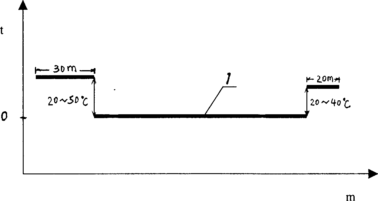
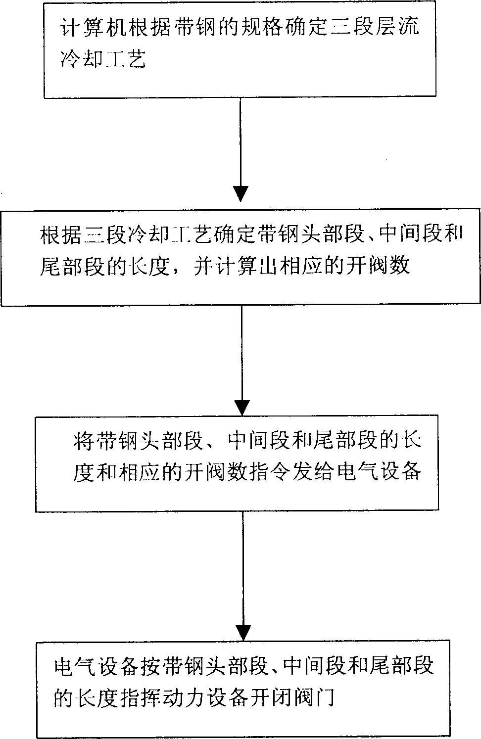
[0015] Embodiment 1 of the present invention takes the strip steel of SS400 steel production 1.5 * 1250mm specification as example, and the target coiling temperature of strip steel 1 is set as 650 ℃, can see that the ideal coiling temperature of its head segment should be greater than The target coiling temperature is 35°C, that is, 685°C, while the coiling temperature of the tail section should be 675°C. According to the three-stage cooling control program (see attached Figure 4 ), first check whether it is three-stage cooling; if so, then determine the three-stage cooling process system (find out the difference between the head section and the tail section and the target coiling temperature); calculate the number of valve openings in the three sections (the layer of the head section The number of flow valves is 6, the middle section is 9, and the tail section is 7), and the respective lengths are determined. Then the electrical equipment directs the power equipment to ope...

Embodiment 2

[0017] Embodiment 2 of the present invention takes Q345A steel to produce strip steel of 16×1550mm specification as an example, the target coiling temperature of strip steel 1 is set at 630°C, and it can be seen from Table 1 that the ideal coiling temperature of the head section should be greater than the target The coiling temperature is 50°C, that is, 680°C, and the coiling temperature of the tail section should be 670°C. According to the three-stage cooling control program, the computer calculates that the number of laminar flow valves in the head section of strip 1 is 28, that in the middle section is 36, and that in the tail section is 30. Finally, the power equipment completes the opening and closing of the valve according to the above-mentioned different valve numbers, thereby realizing the three-stage laminar flow cooling process of the hot-rolled strip steel.


PUM


Abstract

The present invention provides a three-section cooling process by laminar flow for hot-rolled steel strip. Said process adopts the computer laminar flow cooling control, and is characterized by that the steel strip can be divided into three sections for cooling, first section is head portion section whose length is 30 m, second section is intermediate section of the steel strip, and third section is the tail portion section whose length is 20 m, and the cooling temperatures of said three sections are respectively controlled in that its intermediate section temp. is equal to the objective coiling temp., its head portion section temp. is 20-50 deg.C higher than that of objective coiling section, and its tail portion section temp. is 20-40 deg.C higher than objective coiling temp. Said invention can improve the performance uniformity of steel strip.

Description

technical field [0001] The invention belongs to strip steel cooling technology, in particular to a three-stage laminar flow cooling process for hot-rolled strip steel. Background technique [0002] In the production process of hot-rolled strip steel, in order to further improve product quality and increase economic benefits, and obtain high-quality mechanical properties of hot-rolled strip steel, after the hot-rolled strip steel leaves the last stand finishing mill and before entering the coiler, it needs to The hot strip is cooled rapidly to control the coiling temperature of the strip. The coiling temperature is the set temperature, also called the target coiling temperature. It is generally believed that the smaller the fluctuation range of the coiling temperature control with the set temperature as the axis, the higher the control accuracy and the better the control level. It also requires uniform cooling over the entire length of the strip to ensure uniform mechanical ...

Claims


Application Information

Patent Timeline
Patent Type & Authority Applications(China)
IPC IPC(8): B21B37/76B21B45/02
Inventor 杨旭吴晓伟关菊杨大军
Owner ANGANG STEEL CO LTD
Why Eureka
Try Eureka