Interferential position measuring device

A position measuring instrument and interference fringe technology, which is applied in the field of interferometric position measuring instruments, can solve problems such as scale grating pollution, and achieve the effect of reducing measurement errors and compact structure

Inactive Publication Date: 2004-03-24
DR JOHANNES HEIDENHAIN GMBH
View PDF3 Cites 20 Cited by
  • Summary
  • Abstract
  • Description
  • Claims
  • Application Information

AI Technical Summary

Problems solved by technology

However, none of the interferometers disclosed in the aforementioned documents meets all the proposed requirements in a satisfactory manner.
[0006] Thus, the system disclosed by US 6,005,667, although less sensitive to misalignment of the scale grating and scanning unit, is as prone to scale grating contamination as before
[0007] It turns out that the disadvantage of the device described in US 5,574,558 is that it is sensitive to fluctuations in the distance between the two relative movable gratings, that is to say, especially in this direction, there are only small assembly tolerances

Method used


Image

  • Interferential position measuring device
  • Interferential position measuring device
  • Interferential position measuring device

Examples


Embodiment Construction

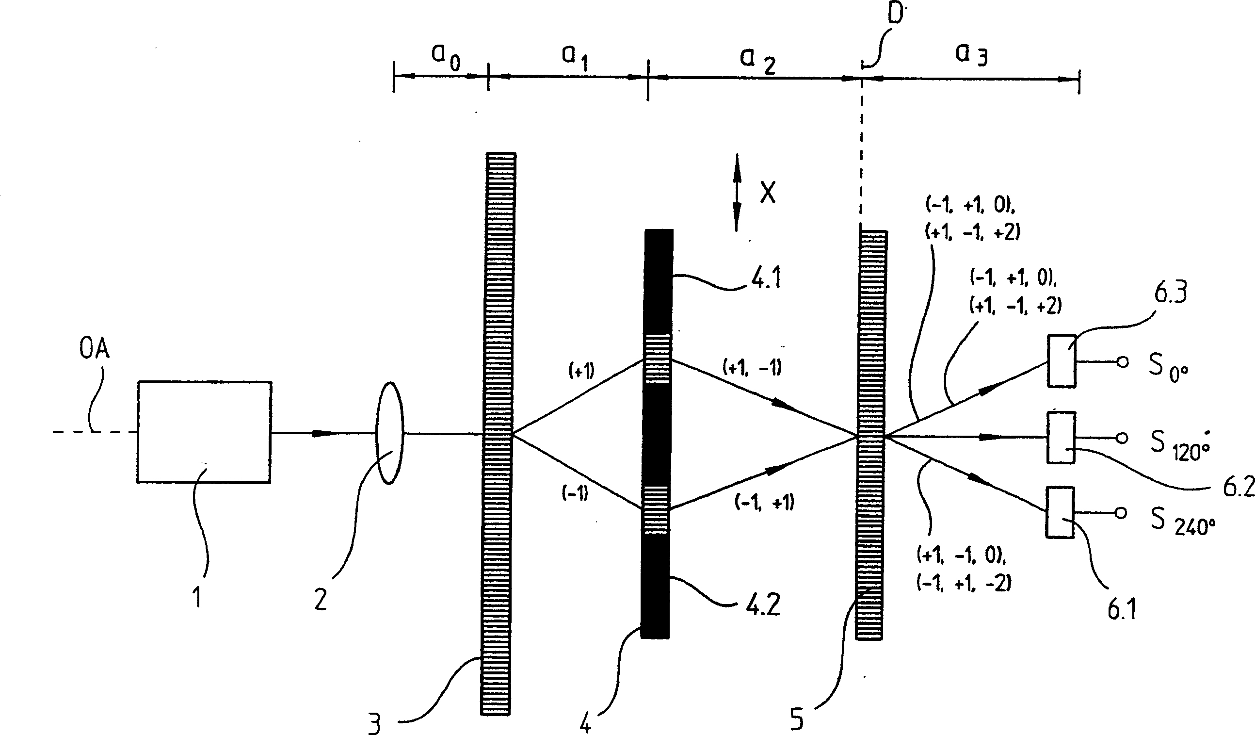
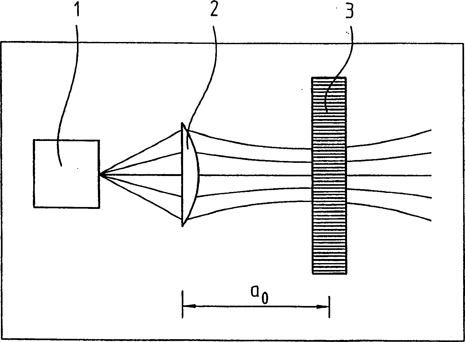
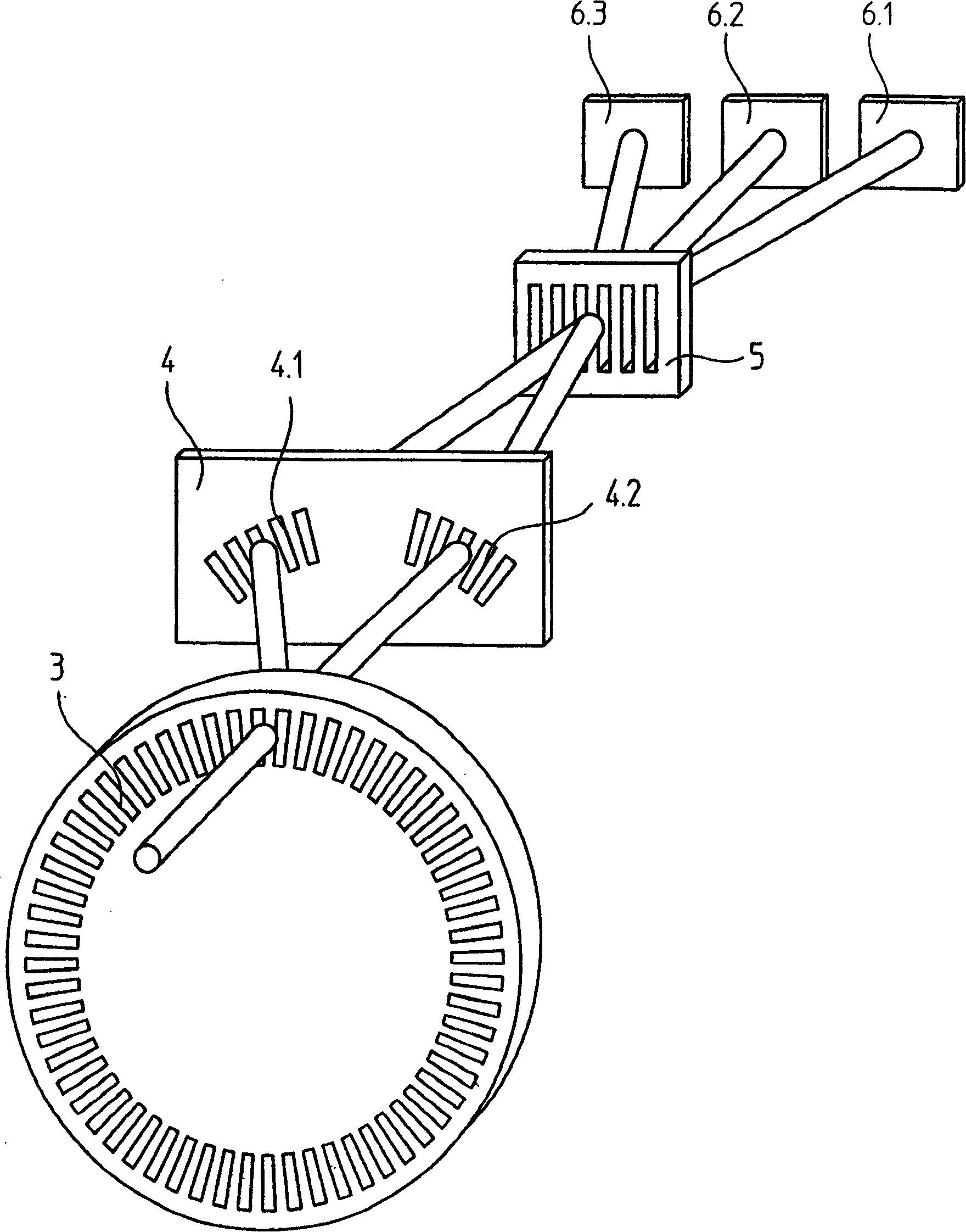
[0024] First, see Figure 1-3 The first variant of the position finder of the present invention will be described. figure 1 The expanded scanning beam path of the position finder is schematically shown here. Position finders are used to determine with high precision the relative position of two objects that are moving relative to each other in at least one measuring direction. exist figure 1 In the schematic schematic diagram shown, the arrows indicate the linear movement in the measuring direction X of the scale grating 3 relative to the remaining elements 1 , 2 , 4 , 5 , 6 which are mounted in a scanning unit. To this end, the scale grating 3 is connected to one of the two objects, and at least one light source 1 and the scanning grating 4.1, 4.2 of the scanning plate 4 are connected to the other of these objects. As can be seen in connection with the following description, instead of the linear measurement direction, it is of course also possible to provide for a rotatio...


PUM


Abstract

Interference position measurement device comprises a light source (1), beam shaping optical element (2), measurement scale grating (3) and two scanning gratings (4.1, 4.2) so that an initial beam is split into two and then into third and fourth and possibly fifth and sixth beams of which at least two recombine in a detector plane (D). If there is a relative movement between the light source, measurement grating and scanning gratings a periodic interference band pattern is generated in the detection plane. Phase shifts are then measured with one of a number of methods. An interferential position measuring arrangement including a light source connected to a first object, which emits a beam of rays in a direction of an optical axis and an optical element arranged downstream of the light source, which converts the beam of rays emitted by the light source into an incoming beam of rays. A scale grating connected to a second object that moves relative to the first object, which splits the incoming beam of rays into a first partial beam of rays, which is propagated into a first spatial direction and a second partial beam of rays, which is propagated into a second spatial direction. A first scanning grating that causes splitting of the first partial beam of rays into third and fourth partial beams of rays and a second scanning grating that causes splitting of the second partial beam of rays into fifth and sixth partial beams of rays, wherein at least two of the third, fourth, fifth and sixth partial beams of rays meet again, and a periodically modulated interferential fringe pattern with a definite spatial interferential fringe pattern period results in a detection plane. A detection arrangement arranged in the detection plane.

Description

technical field [0001] The present invention relates to interferometers. Background technique [0002] Interferometers are well known for the precise measurement of position, which utilize the phenomenon of grating diffraction to generate high-resolution and position-dependent scanning signals. When the scale grating is moved relative to a scanning unit, phase shifts are produced in the sub-beams with deflected diffractive orders, which are proportional to the change in the optical path. In order to calculate or grasp the phase shift at that time, the different resolved sub-beams or diffraction orders are superimposed and interfered. In the case of movement, a periodic modulation of the interference fringe pattern is obtained, which modulation can be grasped using a suitable optoelectronic detector. Regarding the situation of this interferometer, it is recommended to refer to Chapter 4 of J. Willhelm's doctoral dissertation "Dreigitterschrittgeber" published in 1978, pages...

Claims


Application Information

Patent Timeline
Patent Type & Authority Applications(China)
IPC IPC(8): G01D5/26G01D5/38
CPCG01D5/38
Inventor W·霍尔扎普费尔M·赫尔曼W·胡伯V·赫菲尔U·本纳K·桑迪
Owner DR JOHANNES HEIDENHAIN GMBH
Why Eureka
Try Eureka