Forced vibration demonstration experiment instrument

A forced vibration, experimental instrument technology, applied in the field of university physics teaching experimental instruments

Inactive Publication Date: 2004-03-31
TSINGHUA UNIV
View PDF0 Cites 14 Cited by
  • Summary
  • Abstract
  • Description
  • Claims
  • Application Information

AI Technical Summary

Problems solved by technology

However, there is no report related to this kind of demonstration experiment in the reference b

Method used


Image

  • Forced vibration demonstration experiment instrument
  • Forced vibration demonstration experiment instrument
  • Forced vibration demonstration experiment instrument

Examples


Embodiment Construction

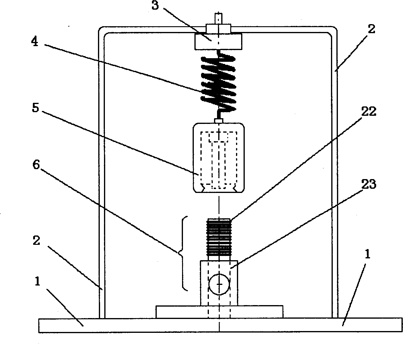
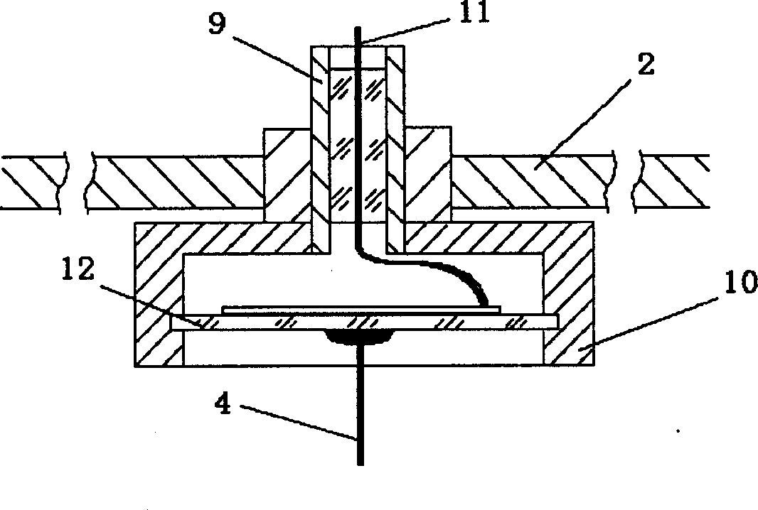
[0008] Embodiments are described below with reference to the drawings. Such as figure 1 As shown, the forced vibration demonstration experiment instrument is mainly composed of base frames 1 and 2, displacement sensor 3, spring vibrator, that is, spring 4, mass block 5, and driving force device 6. The upper end of the spring 4 of the spring vibrator is connected to the displacement sensor 3, and the lower end of the mass block 5 is connected with the driving force device. The displacement sensor 3 is composed of a piezoelectric ceramic sheet 12 embedded in the fixed cylinder 10, the structure is shown in figure 2 , piezoelectric ceramic sheet 12, diameter φ35mm, thickness about 0.50mm, base frequency about 1200Hz.; fixed cylinder 10 is made of duralumin or brass material, outer diameter may be φ50mm; piezoelectric ceramic sheet 12 is embedded in it Between and around, it is firmly connected with the fixed cylinder 10 and serves as an electrode (ground electrode). The other...


PUM


Abstract

A forced oscillation demonstration test instrument comprising a base frame, a displacement sensor, a spring oscillator (spring and mass block) and a propulsion unit, wherein the voltage between the two poles of the spring oscillator is in proportional to the tension force, and the spring tension force is proportional to the displacement of the oscillator mass. When the coil is powered by alternating current, the counteracting force of the ampere force exerted on the coil will be the driving force for the excitation of spring oscillator oscillating, the driving force signal can be represented by the voltage on the resistor in series connection with the coil.

Description

Technical field: [0001] The patent of the invention relates to an experimental instrument for demonstrating forced vibration, which belongs to the field of university physics teaching experimental instruments. Background technique: [0002] The establishment of the physical image of the forced vibration of the spring oscillator is one of the basic requirements of the university physics course. To establish this physical image, it is necessary to understand the variation law of the size of the vibration waveform of the forced vibration of the vibrator and its relative position with the frequency of the driving force. The former is called the amplitude-frequency characteristic, and the latter is called the phase-frequency characteristic. The teaching requirements of college physics require corresponding physics demonstration experiments. However, there is no report related to this demonstration experiment in the reference books of university physics teaching and related teach...

Claims


Application Information

Patent Timeline
IPC IPC(8): G09B23/10
Inventor 路峻岭汪荣宝
Owner TSINGHUA UNIV
Why Eureka
Try Eureka