Dry-process flue gas desulfurizing method using combined gas jet

A dry-process flue gas desulfurization and flue gas technology, which is applied in the direction of separation methods, chemical instruments and methods, and dispersed particle separation, can solve problems such as not being able to meet the fluidization requirements of large-scale flue gas desulfurization reactions, and achieve widening load changes The effect of adaptability, improving utilization rate and enhancing mass transfer effect

Inactive Publication Date: 2004-04-14
WUHAN KAIDI ELECTRIC POWER CO LTD
View PDF2 Cites 10 Cited by
  • Summary
  • Abstract
  • Description
  • Claims
  • Application Information

AI Technical Summary

Problems solved by technology

In particular, the dry desulfurization technology cannot meet the fluidization requirements of large-scale flue gas desulfurization reactions when the unit capacity is large

Method used


Image

  • Dry-process flue gas desulfurizing method using combined gas jet
  • Dry-process flue gas desulfurizing method using combined gas jet
  • Dry-process flue gas desulfurizing method using combined gas jet

Examples


Embodiment Construction

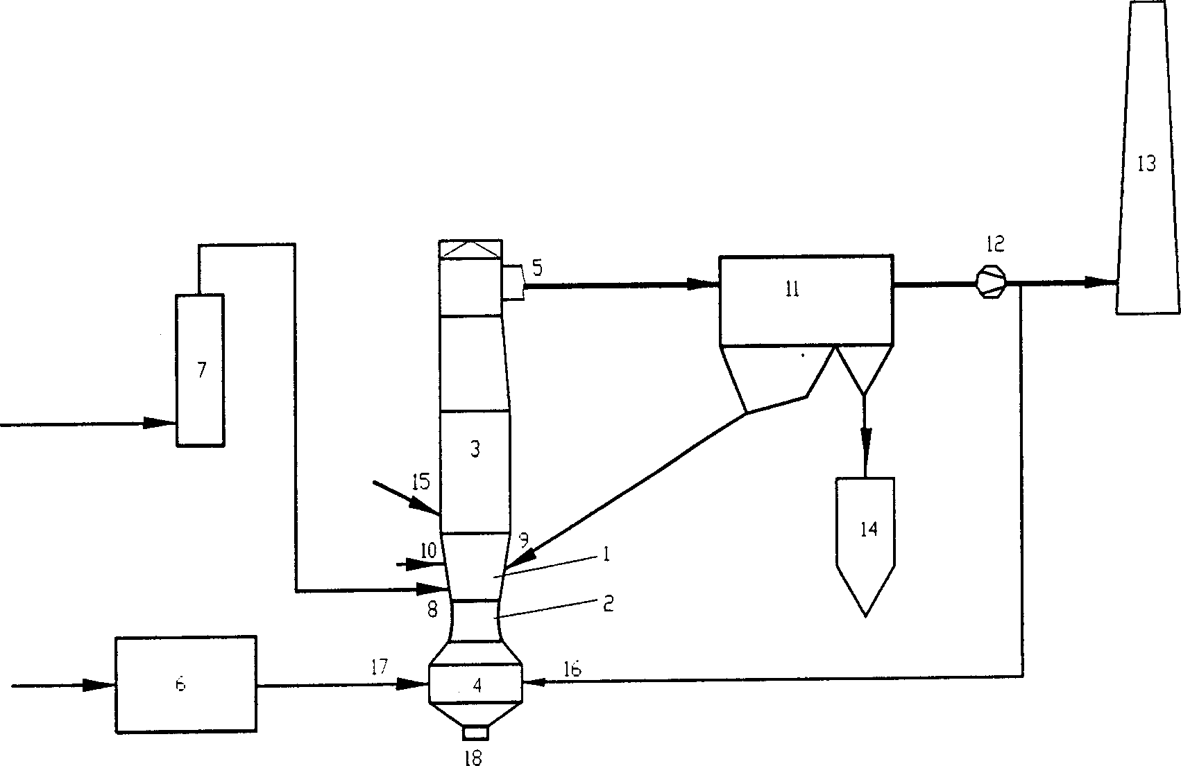
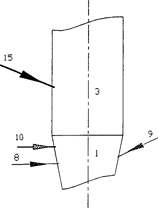
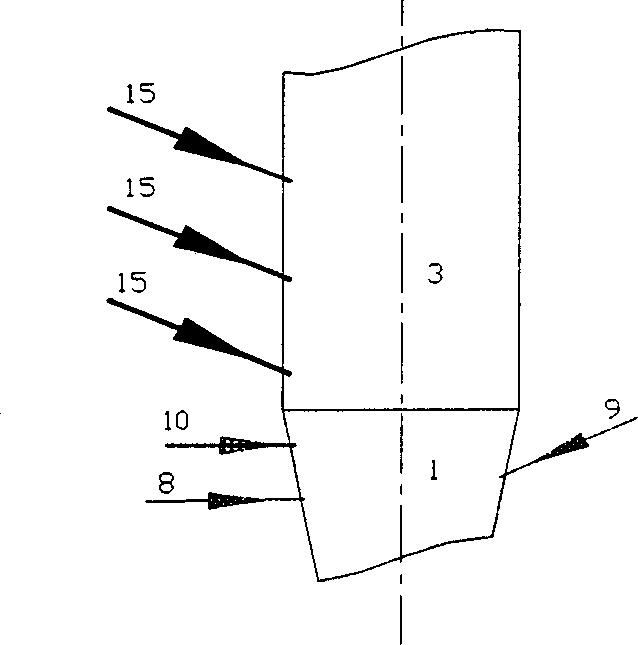
[0028] General application The desulfurization reaction tower of the present invention includes: a flue gas mixing chamber at the bottom of the tower, a flue gas injection device (Venturi nozzle, air distribution device) in the flue gas mixing chamber, a water supply atomizing nozzle, a feeding device, and a feeding device , flue gas jet nozzle, desulfurization reaction tower body, separation (static, cloth bag, inertia, etc.) device outside the desulfurization reaction tower, desulfurization tower flue gas recirculation device. In the present invention, the combined flue gas jet is sprayed into the middle or upper part of the desulfurization reaction tower, thereby changing the flow characteristics of the middle and upper regions of the desulfurization tower, strengthening the turbulence intensity, and forming a new vortex area, so as to effectively organize the gas, solid and gas in the desulfurization reaction tower. Full mixing of liquid three phases and speed slip.

[002...


PUM


Abstract

The invention discloses a drying smoke desulfurizing method by using combined smoke jet. The character is that it adds a smoke jet nozzle above the water nozzle and desulfurizing agent muzzle. It realizes the fully combination of gas, solid and liquid in the desulfurizing reaction tower, increases the desulfurizing efficiency.

Description

technical field [0001] The invention relates to a dry flue gas desulfurization method using a combined flue gas jet, which belongs to the technical field of flue gas desulfurization, and particularly relates to a dry desulfurization system and process in flue gas discharged from various combustion equipment. Background technique [0002] The control of sulfur dioxide gas pollution has always been the focus of environmental protection in most countries in the world, and the pollutants produced by it are the largest source of pollution that has caused damage to the ecological environment in my country. At present, it has become the top priority of air pollution control in my country. [0003] At present, the treatment of sulfur dioxide generally adopts the wet lime-gypsum method (W-FGD) in foreign countries. Although the above-mentioned method has a good removal effect, it has huge investment, large water consumption, large floor area, complex system, There are a series of pro...

Claims


Application Information

Patent Timeline
Patent Type & Authority Applications(China)
IPC IPC(8): B01D53/83
Inventor 刘亚丽张泽胡永锋李雄浩林冲张颉
Owner WUHAN KAIDI ELECTRIC POWER CO LTD
Why Eureka
Try Eureka