Method and device for obstacle detection and distance measurement by infrared radiation

A technology of infrared radiation and infrared rays, which is applied in the field of remote control mechanical devices, devices for detecting the second object and distance, and can solve problems such as trouble, interference distance measurement, etc.

Inactive Publication Date: 2004-04-14
威尼
View PDF0 Cites 19 Cited by
  • Summary
  • Abstract
  • Description
  • Claims
  • Application Information

AI Technical Summary

Problems solved by technology

[0014] For the method using signal phase difference, the existence of interference brings trouble to the measurement of distance

Method used


Image

  • Method and device for obstacle detection and distance measurement by infrared radiation
  • Method and device for obstacle detection and distance measurement by infrared radiation
  • Method and device for obstacle detection and distance measurement by infrared radiation

Examples


Embodiment Construction

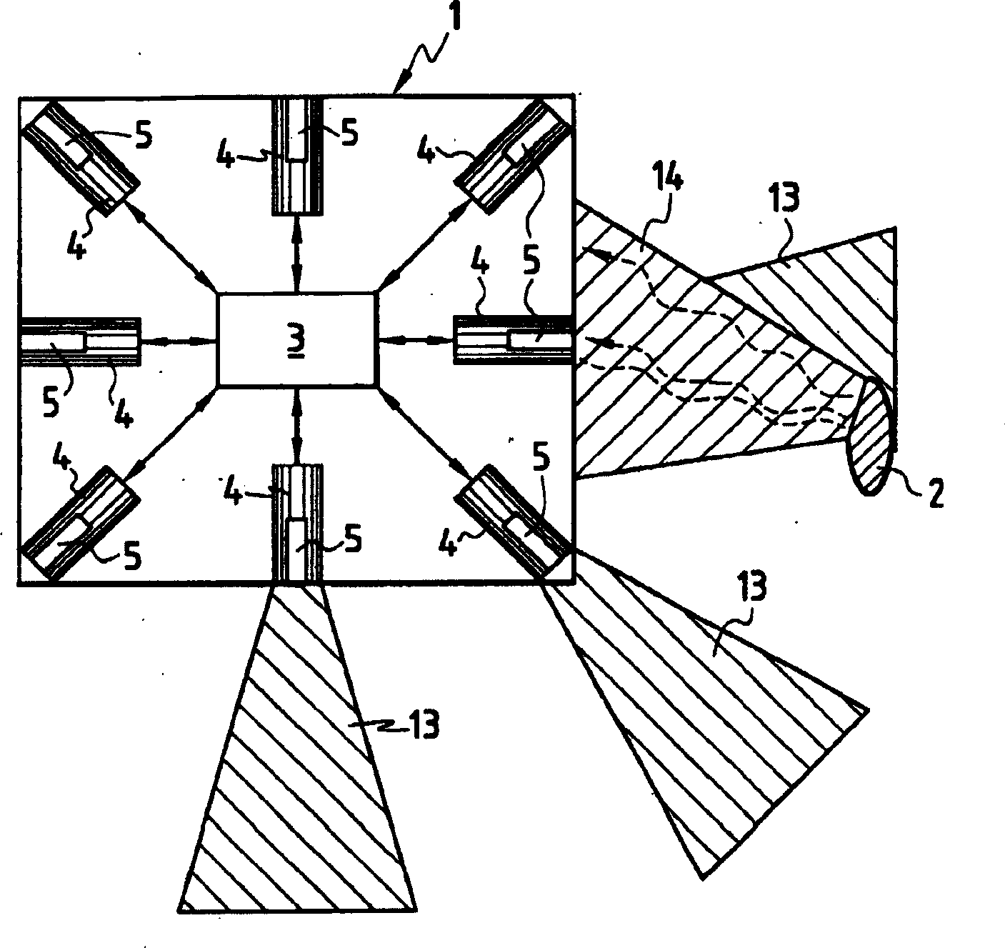
[0102] FIG. 1 is a schematic diagram of installing eight sensors on a moving object such as a robot 1 . These sensors face eight directions. The figure shows the cone 13 formed by the infrared emission and the infrared rays 14 reflected back to the receiver 5 when hitting the obstacle 2 .

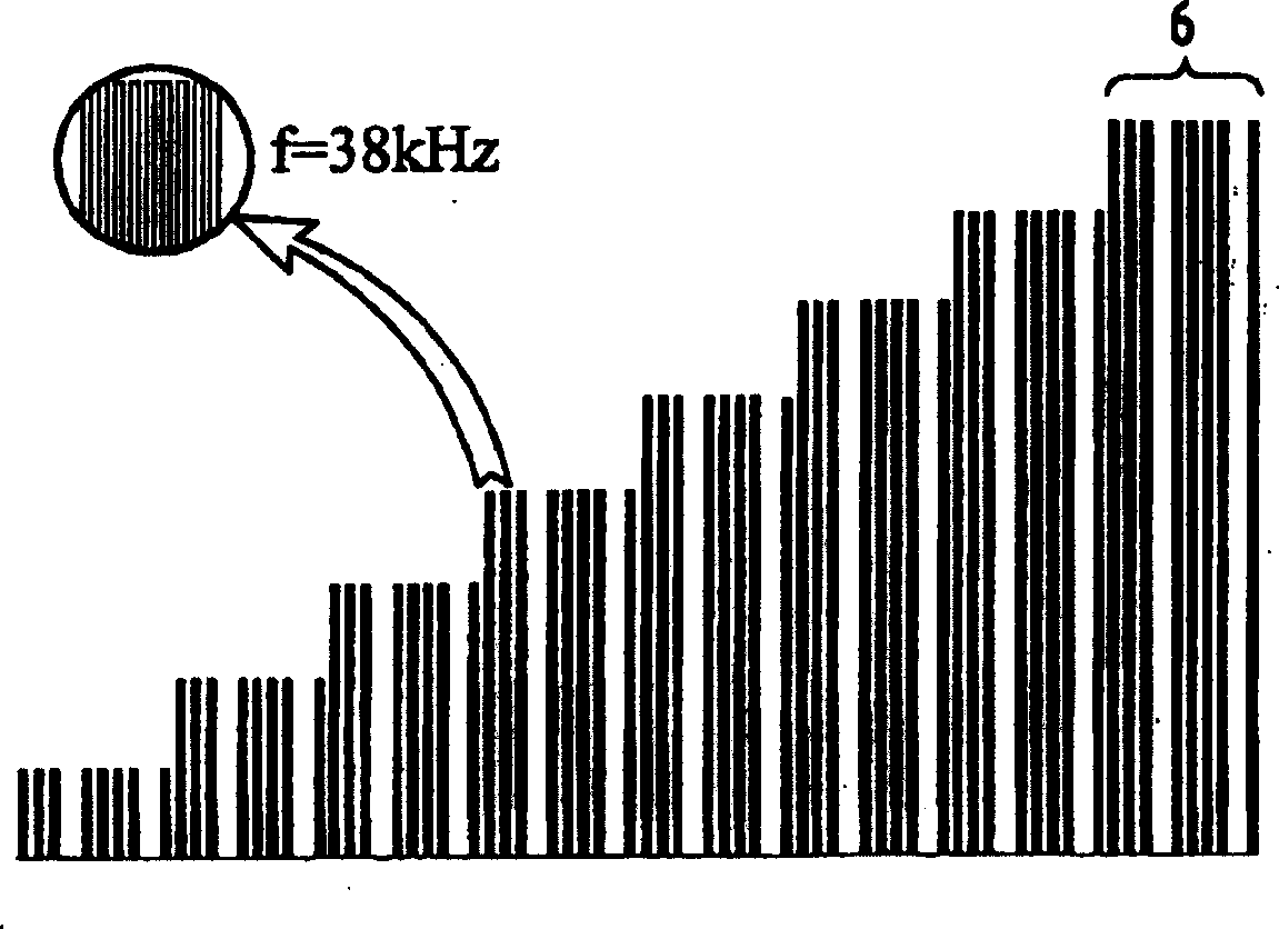
[0103] Figure 2 shows the eight levels of current in the diode emitter (16 in total), that is, the eight levels of the power of the wave emitted by the diode emitter, the corresponding 10-bit digital signature is "1110111101", and the infrared wave is based on the frequency Transmitter for 38 kHz pulsed mode.

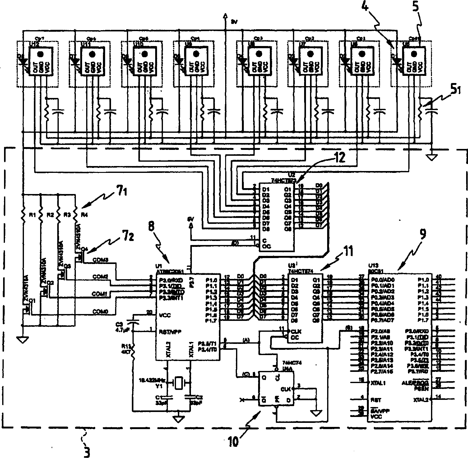
[0104] Figure 3 is a schematic diagram of an electronic assembly showing eight diode transmitters 4 (D1 to D8) connected to a microcontroller 8, eight receivers 5 (U5 to U12) and an external processor 9 (U13). The communication between processors 8 and 9 is via a pendulum register 11 (U3).

[0105] We implemented a ranging system with eight sensors (Cp0 to Cp7) forming an ensemble...


PUM


Abstract

The invention concerns a method for measuring distance between a first object (1) and a second object (2) which consists in: a) emitting an infrared wave radiation (3) from an emitter (4) fixed on the first object (1), said radiation (3) being emitted towards said second object (2); and b) detecting the return of said radiation after it has been reflected by said second object (2) on a receiver (5) fixed on said first object (1) proximate to said emitter (4). The inventive method is characterised in that it consists in: 1/ gradually varying the power of the infrared radiation emitted by said emitter (1) until it reaches a detection power (Ps) corresponding to the power of the wave emitted as from which the radiation reflected by said second object is detected by said receiver; and 2/ calculating the distance (D) between said first object (1) and said second object (2) from the value of said detection power, by establishing an equating correlation between said distance (D) and said detection power. The invention also concerns a device for detection and distance measurement.

Description

technical field [0001] The method relates to a method of measuring the distance between a first object and a second object. The present invention also relates to a method for detecting the second object. The second object may be an obstacle of unknown orientation that may exist around the first object. The first object is mainly a remote-controlled mechanical device such as a robot. The invention also relates to a device for detecting obstacles and measuring the distance between a first object and a second object. [0002] Specifically, the present invention relates to a non-contact method for detecting obstacles and measuring distances using an infrared transmitter and an infrared receiver. Background technique [0003] Various systems exist for contactless distance measurement, which can be classified according to the light beam used (laser, infrared or ultrasonic) or the technique of the measurement system (interference, measurement of travel time, truncation of the beam...

Claims


Application Information

Patent Timeline
Patent Type & Authority Applications(China)
IPC IPC(8): G01S17/931G01S17/04G01S17/10G01S17/87G01S17/88
CPCG01S17/936G01S17/026G01S17/87G01S17/10G01S17/04G01S17/931G01C3/02
Inventor 伊万·拉瓦瑞克劳伦特·特迈尔
Owner 威尼
Why Eureka
Try Eureka