Supercharge Your Innovation With Domain-Expert AI Agents!

Dispersion displacement optical fibre

A technology of dispersion-shifted optical fiber and dispersion, which is applied in clad optical fiber, multi-layer core/clad optical fiber, optics, etc. It can solve problems such as non-linear optics and nonlinear optics, and achieve reduced number of installations, low price, and high transmission capacity increased effect

Inactive Publication Date: 2004-05-12
FURUKAWA ELECTRIC CO LTD
View PDF1 Cites 2 Cited by
  • Summary
  • Abstract
  • Description
  • Claims
  • Application Information

AI Technical Summary

Problems solved by technology

However, the optical fiber disclosed in Patent Document 1 is intended to be used in the wavelength region within the range of 1525 to 1565 nm, regardless of the use in the wavelength region within the range of 1565 to 1625 nm.
[0006] Then, in a WDM transmission system combining such an optical fiber amplifier with the optical fiber disclosed in Patent Document 1, even in the wavelength region where the optical fiber amplifier has gain, the optical fiber of Patent Document 1 is used, and it is easy to achieve near zero dispersion wavelength. Non-linear optical phenomenon occurs, so there is a problem that the signal light near the zero dispersion wavelength cannot be used for long-distance transmission

Method used


Image

  • Dispersion displacement optical fibre
  • Dispersion displacement optical fibre
  • Dispersion displacement optical fibre

Examples


Embodiment Construction

[0024] Preferred embodiments of the dispersion-shifted optical fiber of the present invention will be described below with reference to the accompanying drawings.

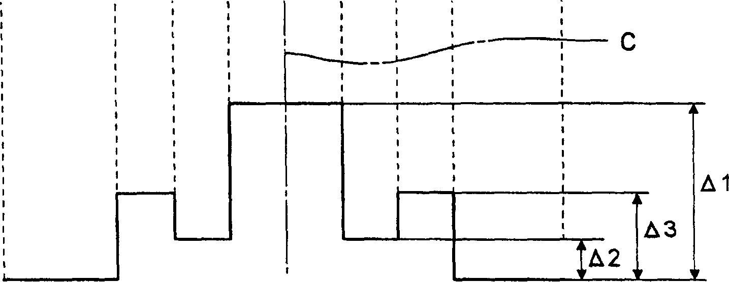
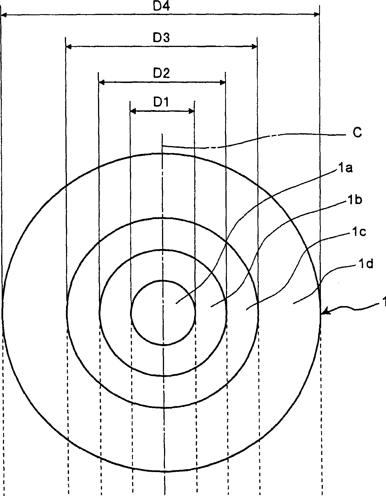
[0025] Figure 1A , 1B represents the dispersion-shifted optical fiber of the first embodiment of the present invention, Figure 1A is the composition diagram of the dispersion-shifted fiber, Figure 1B is a graph showing the refractive index distribution. In the dispersion-shifted optical fiber 1 of the first embodiment, around the central core 1a (refractive index=n1, outer diameter D1) having the optical axis center C, the second core 1b (refractive index=n2, outer diameter D2 ), the third core 1c (refractive index=n3, outer diameter D3), and cladding 1d (refractive index=n2, outer diameter D4) are formed in concentric circles. In this dispersion-shifted fiber 1, by making the refractive index of each part satisfy the relationship of n1>n3>n2, the relative refractive index of the central core 1a, the second cor...


PUM


Abstract

Disclosed is a dispersion shifted fiber, which has zero dispersion wavelength on a long wavelength side beyond 1640 nm, a wavelength dispersion of -1.0 to -10.0 ps / nm / km at a wavelength range of 1530-1625 nm, a dispersion slope of less than 0.07 ps / nm<2> / km, a polarization mode dispersion of not more than 0.1 ps / (km)<1 / 2 >at a wavelength of 1550 nm, and a core cross-sectional area of 40-70 mum<2 >at the wavelength of 1550 nm.

Description

technical field [0001] The present invention relates to a dispersion shifted fiber (Dispersion Shifted Fiber) used as an optical transmission line in a VDM wavelength division multiplexing (VDM wavelength division multiplexing) transmission system that multiplexes signal lights of multiple wavelengths for optical transmission. Background technique [0002] A WDM transmission system using an optical fiber network can transmit large-capacity information over a long distance, and the system includes: a signal transmitter, which transmits signal lights of multiple wavelengths; an optical fiber, which transmits these signal lights; a signal receiver, the A signal receiver receives these optical signals; an optical amplifier, etc., which amplifies the signal light. For such a WDM transmission system, attempts have been made to widen the width of the wavelength region of signal light in order to increase the transmission capacity. [0003] In this case, in order to suppress the wa...

Claims


Application Information

Patent Timeline
Patent Type & Authority Applications(China)
IPC IPC(8): G02B6/036
CPCG02B6/02257G02B6/03644G02B6/02014G02B6/02285G02B6/02238
Inventor 高桥文雄
Owner FURUKAWA ELECTRIC CO LTD
Features
  • R&D
  • Intellectual Property
  • Life Sciences
  • Materials
  • Tech Scout
  • Unparalleled Data Quality
  • Higher Quality Content
  • 60% Fewer Hallucinations
Learn More