Microwave power cell, chemical reactor and power converter

A reaction container and battery technology, applied in chemical instruments and methods, physical/chemical process catalysts, chemical/physical/physical chemical processes, etc.

Inactive Publication Date: 2004-05-12
BRILLIANT LIGHT POWER
View PDF3 Cites 14 Cited by
  • Summary
  • Abstract
  • Description
  • Claims
  • Application Information

AI Technical Summary

Problems solved by technology

In addition, further catalytic tra

Method used


Image

  • Microwave power cell, chemical reactor and power converter
  • Microwave power cell, chemical reactor and power converter
  • Microwave power cell, chemical reactor and power converter

Examples


Embodiment Construction

[0291] The following preferred embodiments of the present invention disclose numerous functional ranges, including but not limited to voltage, current, pressure, temperature and the like, which are provided as illustrative examples only. From the detailed description, those skilled in the art will easily avoid undue experimentation and practice the invention in other functional areas to obtain the desired results.

[0292] 1. Batteries, hydride reactors and energy converters

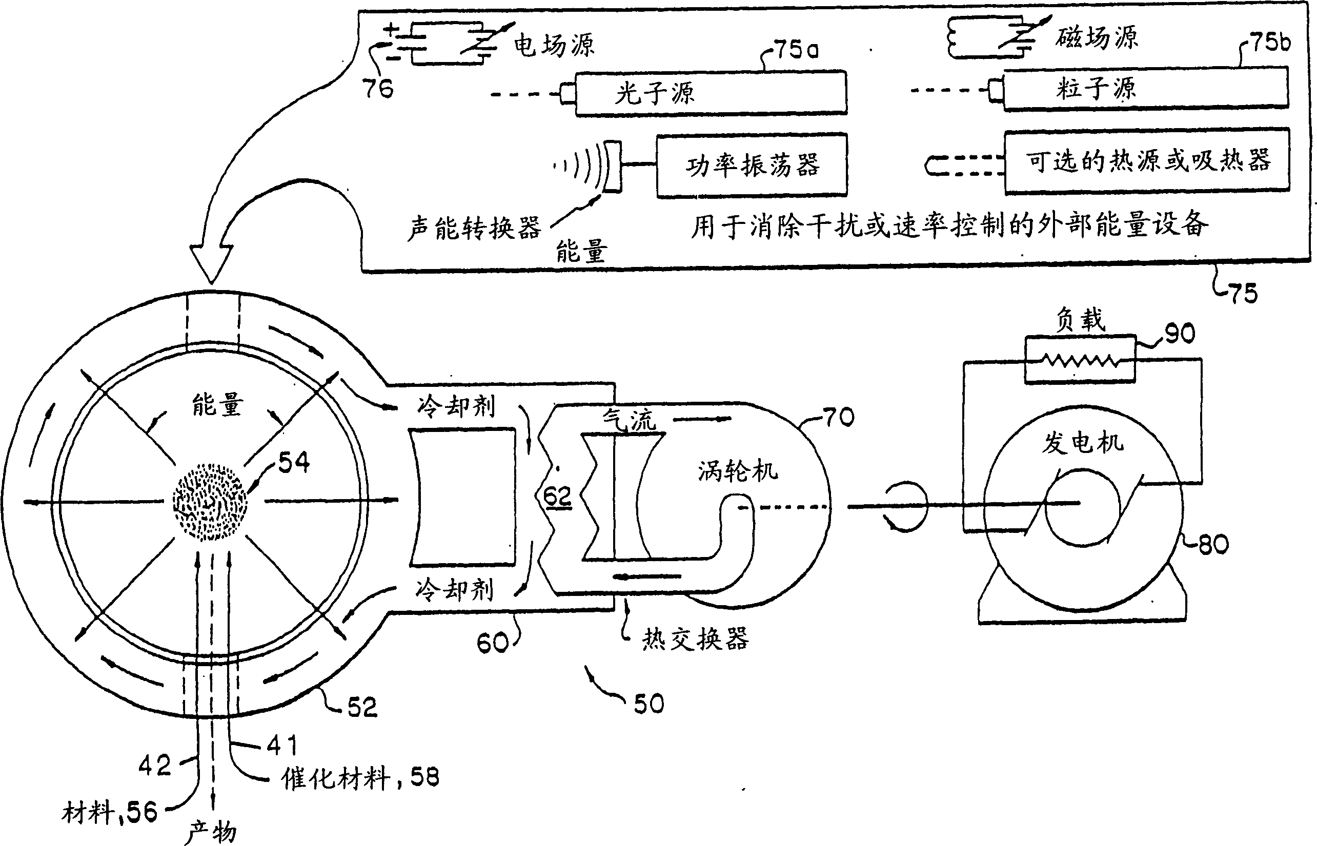
[0293] One embodiment of the invention involves including figure 1 The power system of the hydride reactor is shown. The hydrino hydride reactor consists of a vessel 52 containing a catalytic mixture 54 . The catalytic mixture 54 is composed of a source of atomic hydrogen 56 supplied via the hydrogen supply channel 42 and a catalyst 58 supplied via the catalyst supply channel 41 . Catalyst 58 has approximately m 2 · 27.21 ± ...


PUM


Abstract

Provided is a power source and/or power converter. The power source includes a cell 910 for the catalysis of atomic hydrogen to form novel hydrogen species and/or compositions of matter comprisi ng new forms of hydrogen. The reaction can be initiated and/or maintained by a microwave or glow discharge plasma of hydrogen and a source of catalyst. The plasma power may be converted to electricity by a magnetohydrodynamic power converter 913 or a plasmadynamic power converter.

Description

technical field [0001] The present invention relates to power supplies and / or energy converters. The power source includes batteries for the catalysis of atomic hydrogen to form new hydrogen species and / or compositions containing new forms of hydrogen. This reaction can be initiated and / or sustained by microwave or glow discharge plasmas of hydrogen and catalytic sources. The energy obtained from the catalytic reaction of hydrogen can be directly converted into electrical energy as it forms or contributes energy to the plasma. According to the adiabatic invariant = constant, the magnetohydrodynamic energy converter can convert the plasma energy into electrical energy by utilizing the directional ion flow formed by the magnetic mirror (magnetic mirror). The energy converter may also contain a magnetic field, using at least one electrode, to generate a voltage across at least one counter electrode connected through a load, thereby separating cations and electrons. Backgrou...

Claims


Application Information

Patent Timeline
IPC IPC(8): G21B3/00B01J19/08B01J19/12B01J35/00C01B3/00H05B6/80H05H1/46
CPCC01B3/00H05B6/806B01J35/002B01J2219/0894B01J19/126Y02E60/324B01J2219/0892B01J19/088B01J2219/0875Y02E30/10B01J19/08
Inventor 兰德尔·L·米尔斯
Owner BRILLIANT LIGHT POWER
Why Eureka
Try Eureka