Arc arrester and switch having same
A technology of arc suppression and arcing, which is applied in the direction of electric switches, high voltage/high current switches, circuit breaker components, etc. It can solve the problems that the arc cannot be actively contacted, the electromagnetic force of the grid is weak, and the arc is difficult to achieve stable interruption. performance, stable electromagnetic force, and the effect of eliminating arcs in large current ranges and small current ranges
- Summary
- Abstract
- Description
- Claims
- Application Information
AI Technical Summary
Problems solved by technology
Method used
Image
Examples
no. 1 example
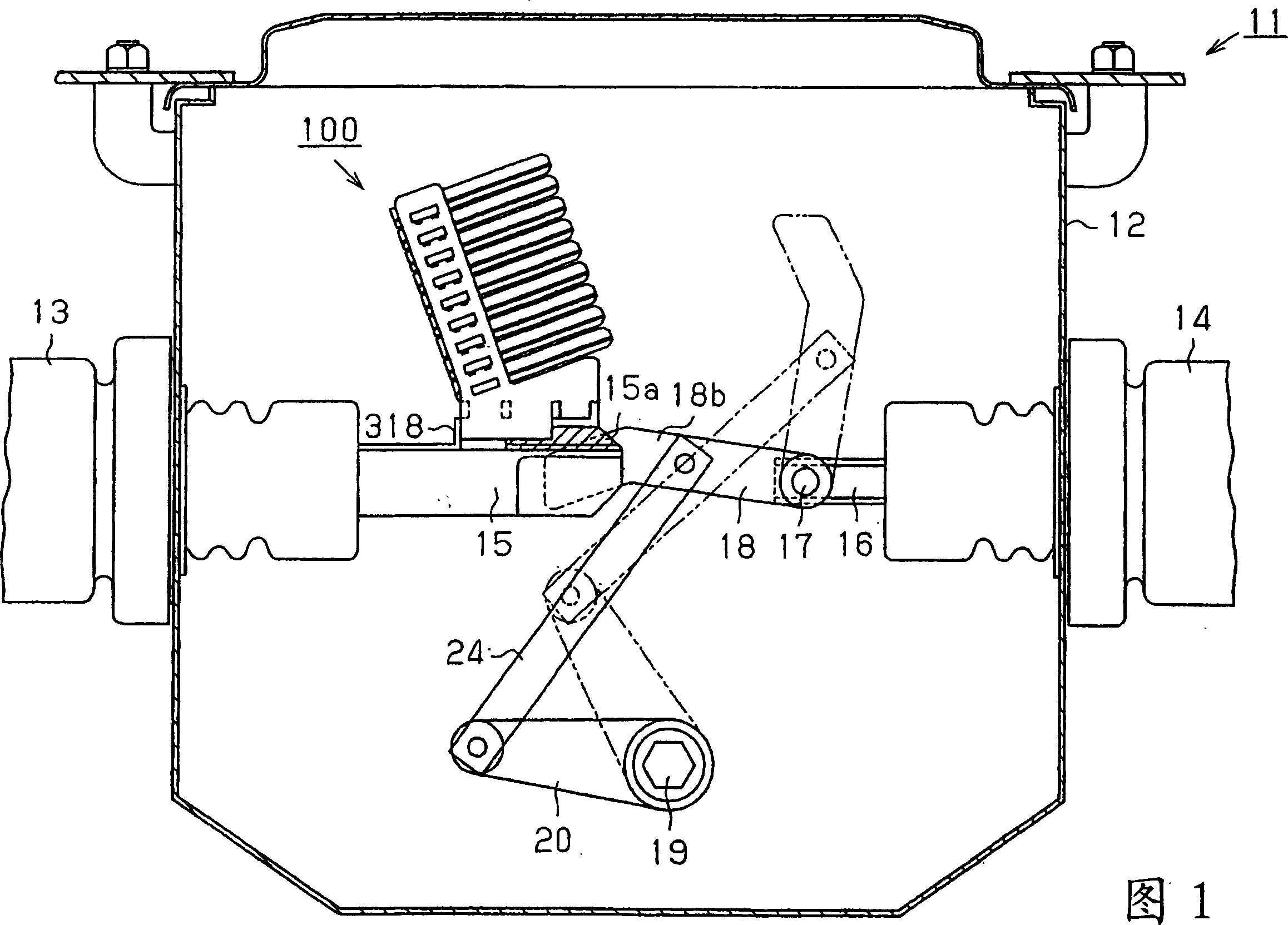
[0085] Hereinafter, for the first embodiment of the present invention embodied as an arc suppression device of a switch, according to Fig. 1 to Figure 9 Be explained.
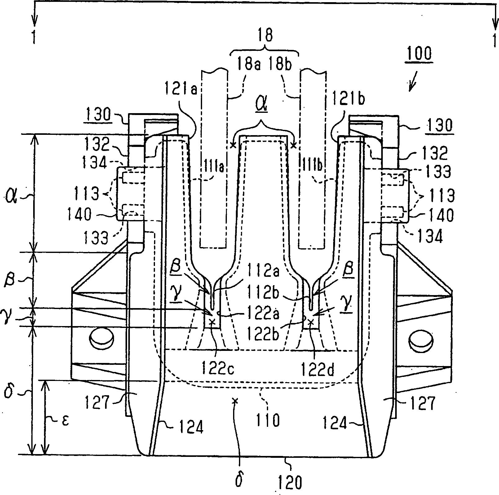
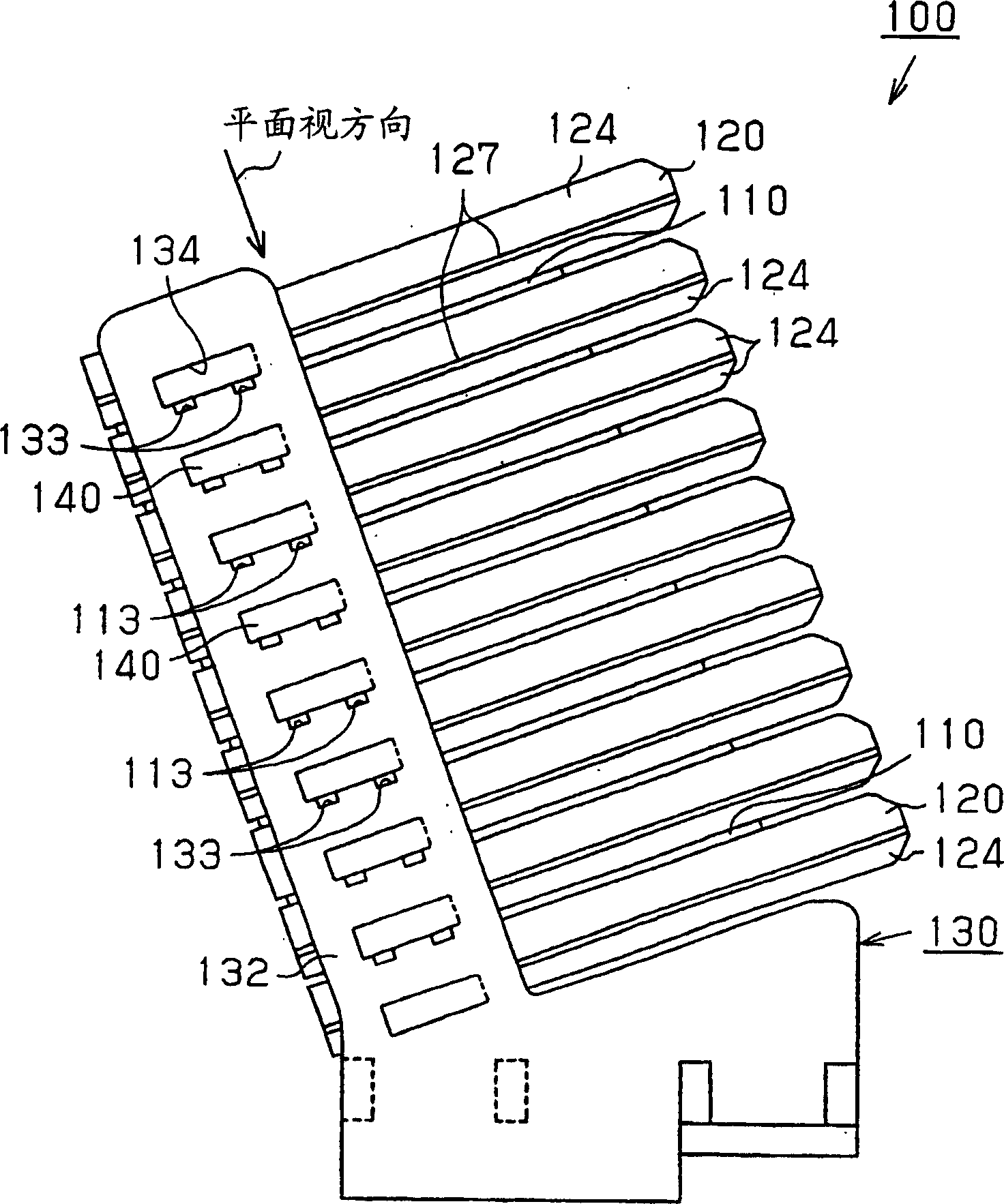
[0086] As shown in Figure 1, on the opposite side walls of the main body shell 12 of the switch 11, the power supply side bushing 13 and the load side bushing 14 are three-phase and each phase is relatively penetrated and supported respectively (a phase division is shown in Figure 1 ). A rod-shaped fixed electrode 15 protrudes from the inner end of the power supply side bushing 13 , and an arc-resistant metal 15 a is fixed to the upper end of the same fixed electrode 15 . A conductive rod 16 protrudes from the inner end of the load-side bushing 14 , and is rotatably supported by the base end of the movable electrode 18 via a shaft 17 on the same conductive rod 16 . like figure 2 The movable electrode 18 has a pair of contact blades 18a, 18b in the shape of a parallel plate as shown by the dashed-two dotted ...
no. 2 example
[0152] Below, according to Figures 10-13 A second embodiment of the present invention will be described.
[0153] like Figure 10 and Figure 11 As shown, an arc suppression device 30 is provided at the inner end of the power measuring sleeve 13 . The arc extinguishing device 30 is composed of a plurality of thin plate-shaped magnetic plates 40 formed of magnetic materials and a plurality of arc extinguishing members 50 formed of a synthetic resin material having insulating and arc extinguishing properties. Arranged in a staggered manner at predetermined intervals.
[0154] magnetic board
[0155] like Figure 12 As shown, the magnetic plate 40 is formed into a W-shaped plate from a magnetic material such as steel. In this embodiment, the thickness d1 of the magnetic plate 40 is 1 mm. A pair of magnetic plate passages 41a, 41b through which the contact blades 18a, 18b can pass, respectively, are formed at predetermined intervals at the front edge of the magnetic plate ...
no. 3 example
[0226] Hereinafter, for the third embodiment of the arc suppression device 100A which embodies the present invention as a switch, according to Fig. 25 to Figure 39 Be explained. Also, the same members as those in the first embodiment are given the same member numbers, and redundant descriptions are omitted.
[0227] As shown in Figure 25, on the opposite side walls 12a, 12b of the main body shell 12 of the switch 11, the power supply side bushing 13 and the load side bushing 14 are three phases and each phase is relatively penetrated and supported respectively (in Figure 25 only represents a phase). The arc extinguishing device 100A is fixed to the inner end of the power supply side bushing 13 (the tip of the fixed electrode 15 ) with a fixing metal 318 . The conductive rod 16 of the load side bushing 14 is rotatably supported by the base end portion of the movable electrode 18 via the shaft 17 . like Figure 26 As shown by the two-dot chain line in the middle, the movabl...
PUM
| Property | Measurement | Unit |
|---|---|---|
| Width | aaaaa | aaaaa |
| Thickness | aaaaa | aaaaa |
| Thickness | aaaaa | aaaaa |
Abstract
Description
Claims
Application Information
 - R&D
- Intellectual Property
- Life Sciences
- Materials
- Tech Scout
- Unparalleled Data Quality
- Higher Quality Content
- 60% Fewer Hallucinations
Browse by: Latest US Patents, China's latest patents, Technical Efficacy Thesaurus, Application Domain, Technology Topic, Popular Technical Reports.
© 2025 PatSnap. All rights reserved.Legal|Privacy policy|Modern Slavery Act Transparency Statement|Sitemap|About US| Contact US: help@patsnap.com


