
Electromagnetic coil spool and terminal assembling structure of clutch for washing machine

An electromagnetic coil and assembly structure technology, applied in the field of clutches, can solve the problems of loose terminals, falling off terminals, and swimming.

Inactive Publication Date: 2004-06-30
LG ELECTRONICS (TIANJIN) APPLIANCES CO LTD
View PDF0 Cites 2 Cited by
  • Summary
  • Abstract
  • Description
  • Claims
  • Application Information

AI Technical Summary

Problems solved by technology

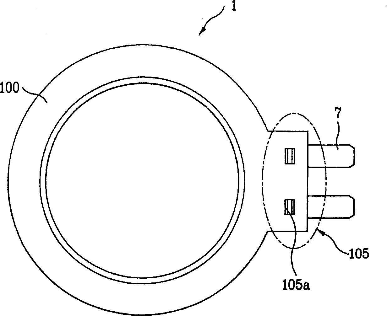
[0029] First, when the terminal (7) is assembled in the terminal insertion hole (105A) formed on the terminal portion (105) of the bobbin (1) made by injection molding, there is no connection between the terminal (7) and the terminal insertion hole (105A). In the case of misalignment, the terminal (7) will be bent and cause defects; or, due to the large diameter of the terminal insertion hole (105A), the inserted terminal (7) is inserted loosely, and there is a phenomenon that it is easy to fall off; or, because The terminal (7) is only supported by the inner side wall of the terminal insertion hole (105A), resulting in unstable fixation and floating phenomenon
[0030] Further, after the coil (2) is wound on the bobbin (1), in order to connect the coil (2) wound on the bobbin (1) to the terminal, it is necessary to wind the coil (2) on the terminal (7) and carry out tinning. Soldering, due to the high temperature of molten tin, the terminal insertion hole (105A) formed on the terminal part (105) will expand due to heat and become larger, causing problems such as the terminal (7) falling off from the terminal insertion hole (105A).

Method used


Image

  • Electromagnetic coil spool and terminal assembling structure of clutch for washing machine
  • Electromagnetic coil spool and terminal assembling structure of clutch for washing machine
  • Electromagnetic coil spool and terminal assembling structure of clutch for washing machine

Examples


Embodiment Construction

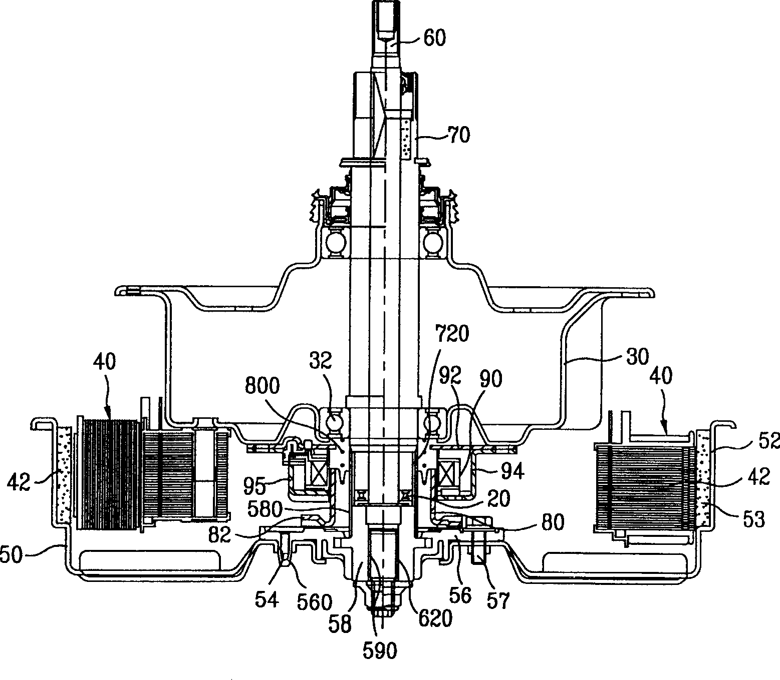
[0058] Refer below Figure 4 to Figure 9 , an embodiment of the bobbin and terminal assembly structure of the electromagnetic coil of the washing machine clutch of the present invention will be described in detail.

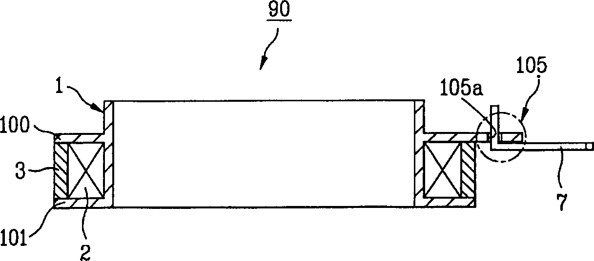
[0059] Such as figure 2 As shown, the electromagnetic coil (90) includes the following structures: a bobbin (1), a coil (2) and a package (3). The spool (1) roughly has a cylindrical shape, and an upper flange (100) and a lower flange (101) are respectively provided at positions separated from each other along the axial direction, and one side of the upper flange (100) is equipped with a The terminal portion (105) of the fixed terminal (7); the coil (2) is wound on the outside of the bobbin (1) between the upper flange (100) and the lower flange (101); in order to make the coil ( 2) not exposed, the package (3) formed by incombustible materials surrounds the outside of the coil (2); for the electromagnetic coil, the terminal portion (105) of the bobbin (1) of t...


PUM


Abstract

The invention is a spool and terminal assembly construction for the electromagnetic coil of the washer clutch, including spool, terminal, coil and package; the terminal part of the spool includes support wall, and the first and second fixing holes, the support wall formed behind the terminal part, the first fixing holes formed on two sides of and in front of the support wall, respectively, directly contacting the front of the support wall, and the second ones formed in front of the first ones; the terminal including underpan, coil linking piece and terminal linking piece, the underpan plated shaped; the coil linking piece perpendicular to the underpan surface, formed by extending from one side behind the underpan and penetrating through the first fixing hole to project to the top of the terminal part, and the terminal linking piece perpendicular to the underpan surface, formed by extending from the other side and projecting to the top of the terminal part in front of the coil linking piece.

Description

technical field [0001] The present invention relates to a clutch of a washing machine, in particular to an electromagnetic coil thereof. Background technique [0002] A general washing machine is a product that removes pollutants adhering to clothes and bedding by using the gentle action of detergent, the friction of water flow generated by the rotation of the washing wings, and the impact action added to the laundry by the agitator. The washing machine senses the amount and type of laundry through the sensor to automatically set the washing method for washing, or the washing water is supplied to an appropriate water level according to the amount and type of laundry and then washed through the control of the computer. [0003] In addition, the fully automatic washing machine in the prior art has the following drive method: the rotational power of the drive motor is transmitted to the washing shaft through the power transmission belt (BELT) and the pulley (PULLEY) to rotate t...

Claims


Application Information

Patent Timeline
IPC IPC(8): D06F37/40F16D27/14
Inventor 安仁根
Owner LG ELECTRONICS (TIANJIN) APPLIANCES CO LTD
Learn More