LED print-head and producing method thereof, and methof for producing LED substrate and pasting method thereof

A technology of LED substrate and manufacturing method, which is applied in the direction of printing, electrical components, circuits, etc., can solve the problems of position deviation of luminous point, deterioration of printing quality, easy warping, etc., achieve sufficient strength, improve reliability, and improve durability The effect of bending deformation and heat deformation strength

Inactive Publication Date: 2004-06-30
SUZUKA FUJI XEROX CO LTD
View PDF6 Cites 9 Cited by
  • Summary
  • Abstract
  • Description
  • Claims
  • Application Information

AI Technical Summary

Problems solved by technology

[0014] In the above-mentioned conventional substrate bonding method, when the size of the above-mentioned substrate B on which the above-mentioned LED chip C is mounted is, for example, an elongated strip shape with a total length of 390 mm, a width of 6 to 10 mm, and a thickness of about 1 mm, the above-mentioned substrate B When the above-mentioned LED chip C is mounted or pasted when there is no viscosity on the surface, the above-mentioned substrate B is likely to warp, and there is a problem that the position of the light-emitting point is shifted and the printing quality is deteriorated.

Method used


Image

  • LED print-head and producing method thereof, and methof for producing LED substrate and pasting method thereof
  • LED print-head and producing method thereof, and methof for producing LED substrate and pasting method thereof
  • LED print-head and producing method thereof, and methof for producing LED substrate and pasting method thereof

Examples


Embodiment approach 1

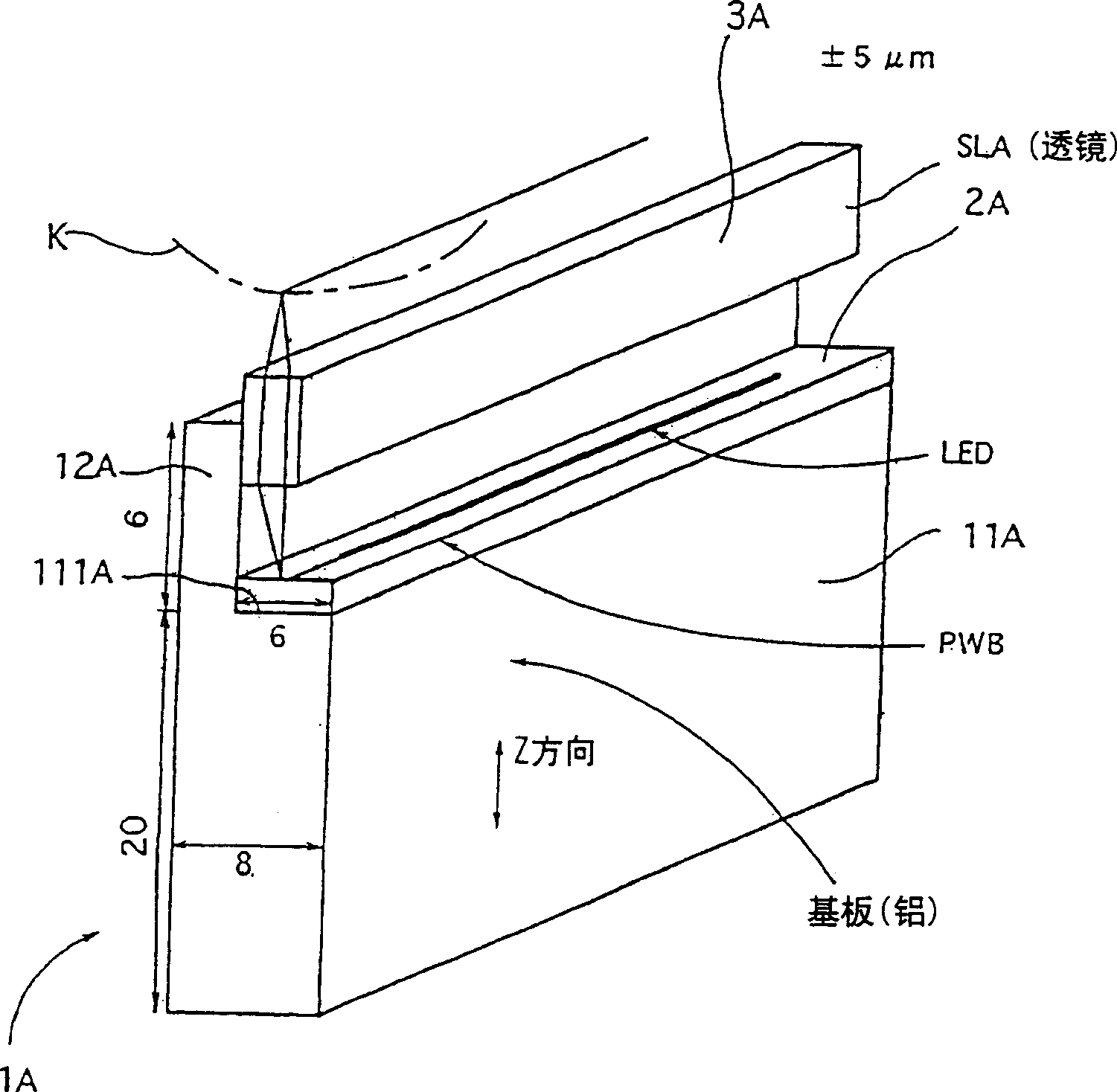
[0100] The LED printing head of this embodiment 1, such as figure 1 As shown, it is composed of a base body 1A disposed opposite to the photosensitive drum K, an LED substrate 2A disposed on the base body 1A, and a lens array 3A. Among them, the base body 1A extends parallel to the axial direction of the photosensitive drum K, and is composed of a large-capacity base portion 11A and a small-capacity protruding portion 12A. The large-capacity base portion 11A is formed opposite to the photosensitive drum K. Surface 111A; the small-capacity protrusion 12A protrudes and extends upward from the above-mentioned facing surface 111A side of the base portion 11A, and is integrally formed. The LED substrate 2A is arranged on the facing surface 111A of the base portion 11A. The lens array 3A is disposed at one end of the protruding portion 12A at a predetermined location between the outer peripheral surface of the photosensitive drum and the upper surface of the LED substrate 2A. The cross...

Embodiment approach 2

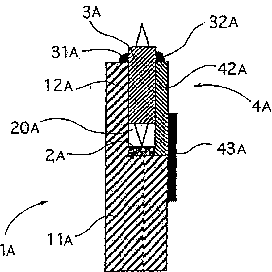
[0118] The LED printing head of this embodiment 2, such as figure 2 As shown, the part of the sealing member 4A that blocks the space 20A between the lens array 3A and the LED substrate 2A is added. This point is different from the above-mentioned first embodiment. The following description focuses on the difference, and the same part is labeled Symbol and description is omitted. The dimensions of each part are the same as in the first embodiment.

[0119] The sealing member 4A is composed of a thin-walled polycarbonate resin and other resin-made shielding members 42A, one end of which faces the other side surface of the lens array 3A on the side surface of the tip portion of the protruding portion 12A, and is sealed by a sealing material 32A and is Fixed; the other end facing the side wall of the base part 11A is sealed by aluminum tape 43A.

[0120] In the LED print head of the second embodiment configured as described above, in addition to the effects of the first embodiment, ...

Embodiment approach 3

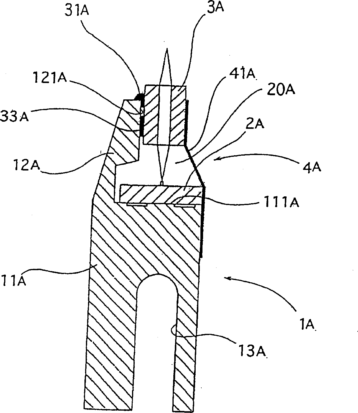
[0122] The LED printing head of this embodiment 3, such as image 3 As shown, a closing member 4A that closes the space between the lens array 3A and the LED substrate 2A is added, and a slightly U-shaped cutout 13A is added to the above-mentioned base part, which differs from the above-mentioned embodiment in these two points 1. The description is centered on the difference, and the same part is marked with the same symbol to omit the description.

[0123] The base portion 11A is composed of a rod-shaped member that extends parallel to the axial direction of the photosensitive drum, and is composed of an aluminum material having a rectangular cross-section with a width of 13.8 mm and a height of 26.5 mm; and on the base portion 11A A horizontally facing surface 111A on which the LED substrate 2A facing the photosensitive drum is arranged is formed.

[0124] In the lower part of the above-mentioned base part 11A, in order to increase the heat radiation area, a cutout part 13A havi...


PUM


Abstract

An LED print head comprising a base body (1) consisting of a large-capacity base unit (11) disposed to extend in parallel to the axis direction of a photosensitive element (K) and formed with a facing upper surface (111) facing the photosensitive element, and a small-capacity projection (12) projecting from a part of the facing upper surface of the base unit to extend and be formed integrally therewith and having a small width in the moving direction of the photosensitive element, an LED substrate (2) disposed on the facing upper surface of the base unit, and lens array (3) disposed at a portion between the facing surface (111) of the element (K) and the upper surface of the LED substrate (2) at one end of the projection (12); and a production method of the LED print head; and a method of producing an LED substrate and a method of pasting an LED substrate.

Description

Technical field [0001] The present invention relates to an LED print head suitable for an electrophotographic copier or printer, a method for manufacturing the same, a method for manufacturing an LED substrate, and a method for adhering an LED substrate. Background technique [0002] The first LED writing head in the past (Japanese Patent: JP 7-108709), such as Picture 12 As shown, the two protruding parts P at the center of the upper surface of the box H having a U-shaped cross section are used to fix the two side surfaces of the rod lens L, thereby arranging the rod lens, so the field of view of the photoreceptor is The angle α is large, and it is difficult to reduce the thickness. Therefore, there is a problem that it is not suitable for tandem colorization. The tandem type is a method in which cyan, magenta, yellow, and black photosensitive drums are arranged in a row using a plurality of imaging drums to form a color image. [0003] In addition, the conventional second LED ...

Claims


Application Information

Patent Timeline
Patent Type & Authority Applications(China)
IPC IPC(8): B41J2/45H01L33/58
CPCB41J2/451
Inventor 植田俊介高木只夫铃木节男堀内武善生驹英之小野博丰田高史夏井小百合
Owner SUZUKA FUJI XEROX CO LTD
Why Eureka
Try Eureka