Control device of linear compressor drive system
A linear compressor and drive system technology, applied in the control input, AC motor control, pump control and other directions related to the system state, can solve the problems such as failure to prevent collision, power consumption, and low possibility of collision.
- Summary
- Abstract
- Description
- Claims
- Application Information
AI Technical Summary
Problems solved by technology
Method used
Image
Examples
Embodiment 1
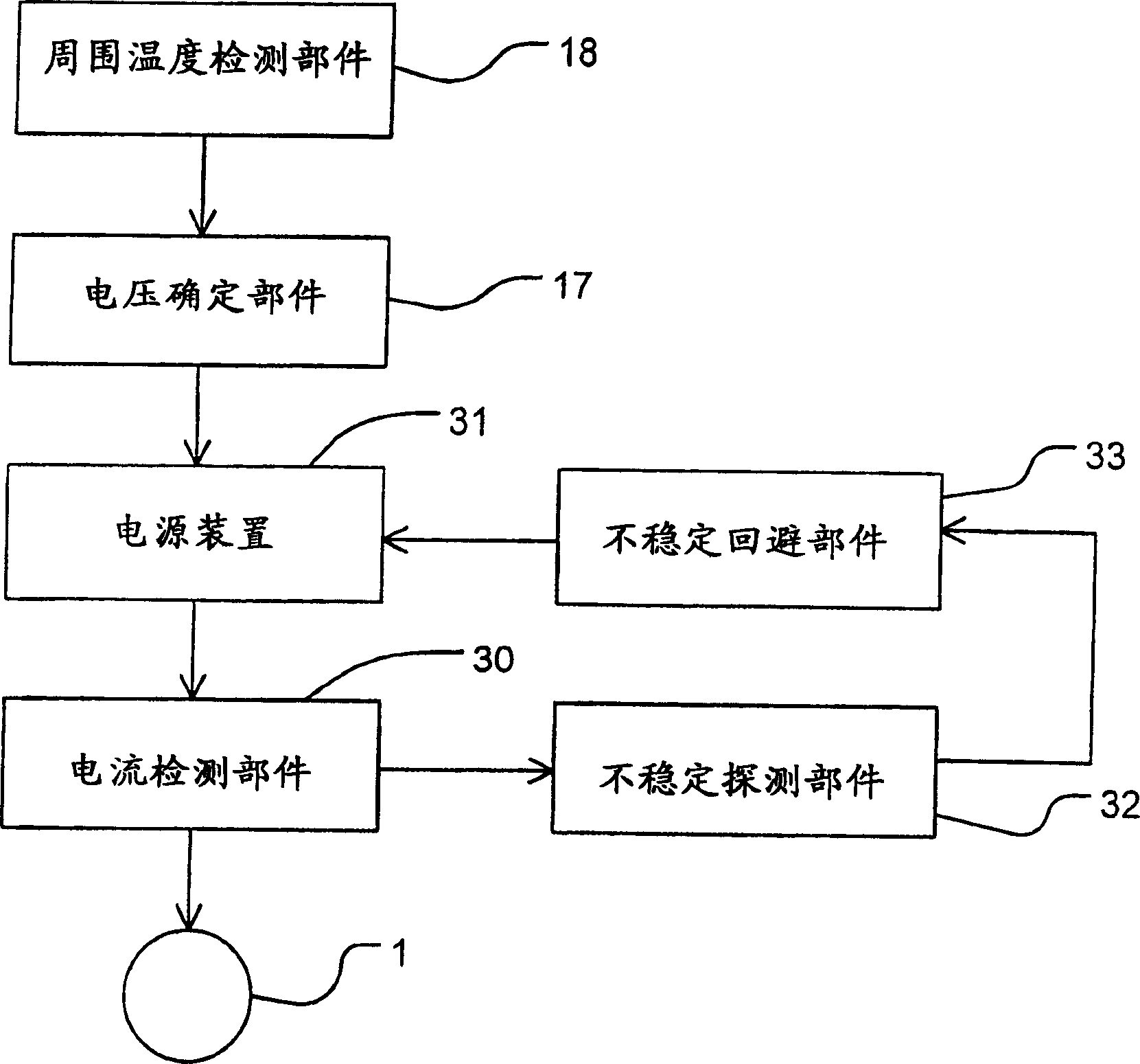
[0050] figure 1 It is a block diagram of the control device of the linear compressor drive system of Embodiment 1 of this invention.
[0051] figure 1 Among them, 30 is a current detecting means for measuring the power supply current supplied from the power supply device 31 to the linear compressor 1 . 32 is an instability detection unit that outputs an instability detection signal based on the output of the current detection unit 30 .
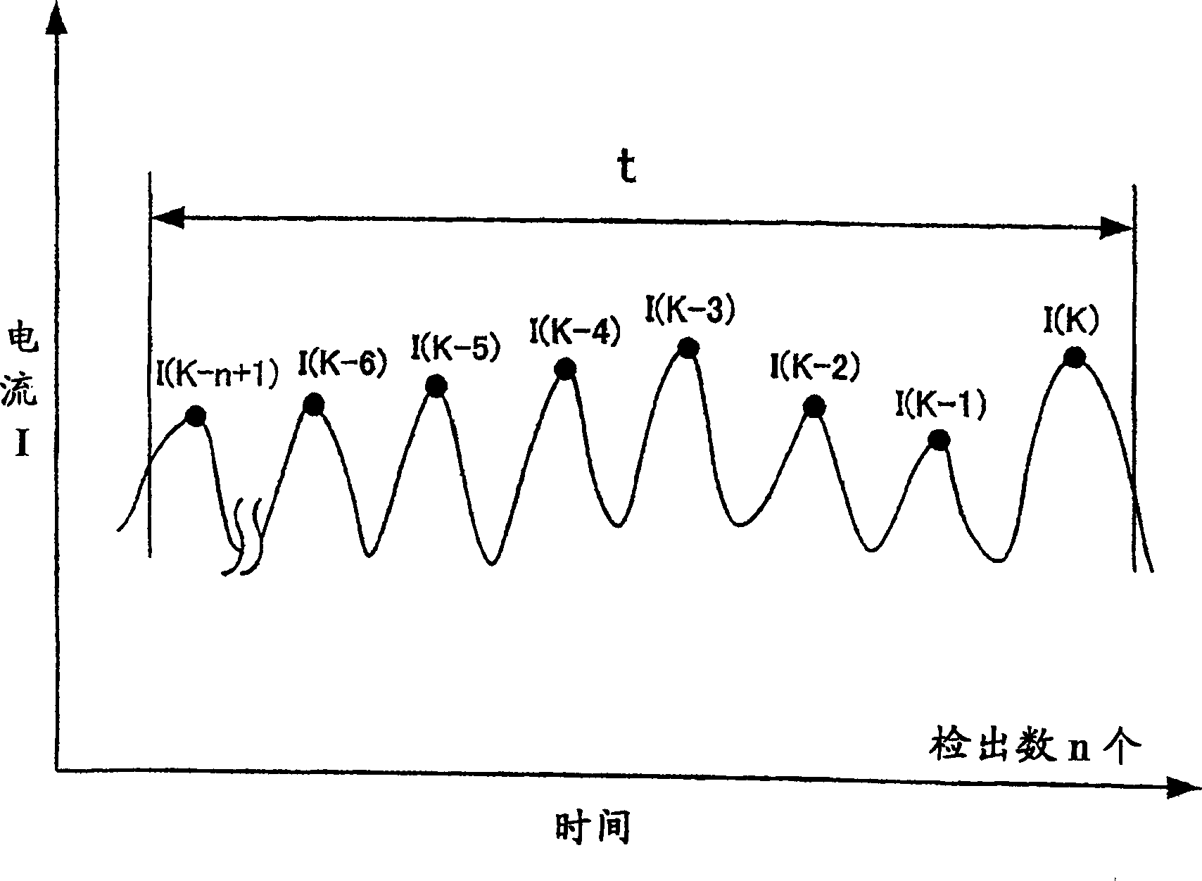
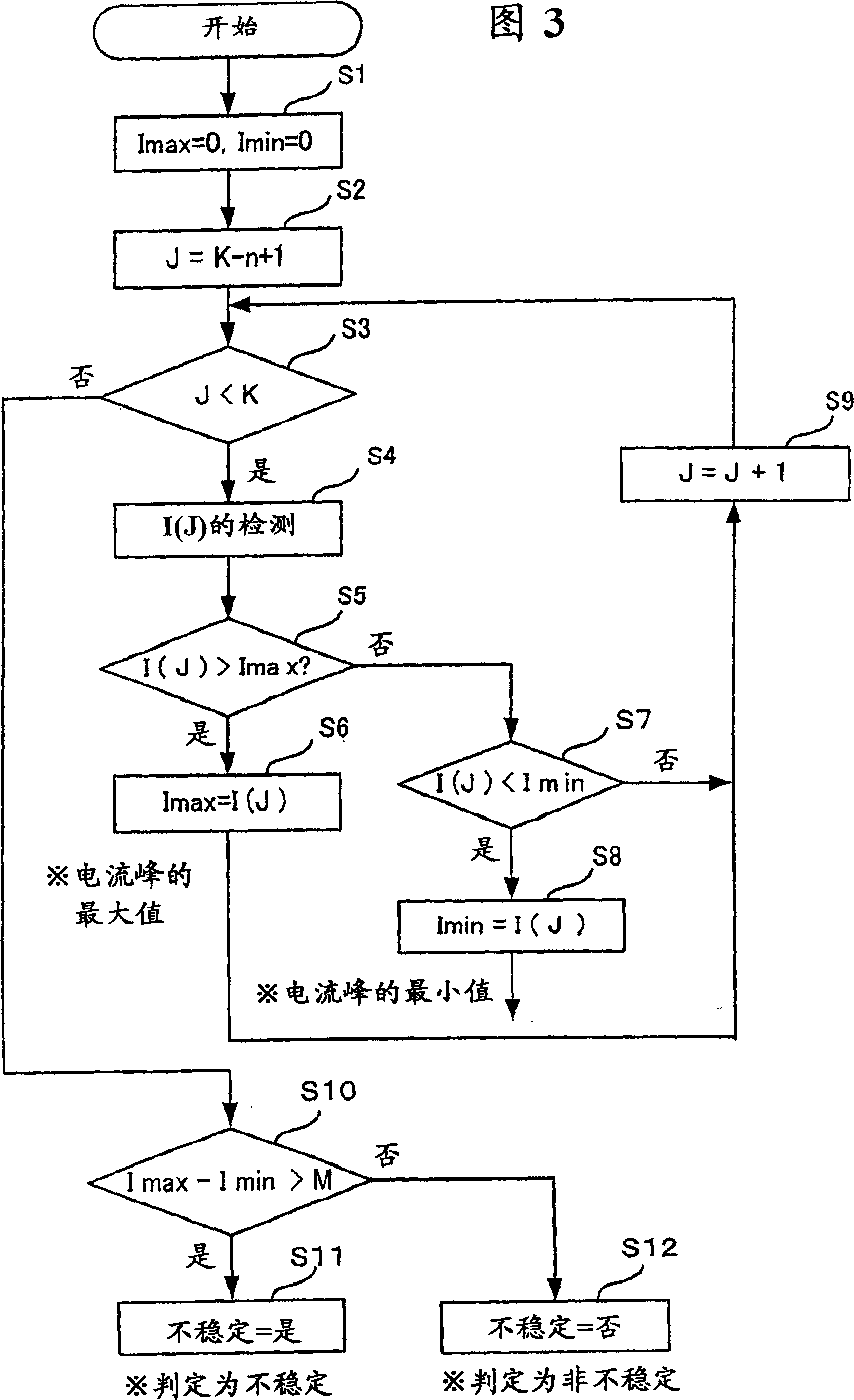
[0052] When the top dead center position of the piston fluctuates greatly, the force acting on the piston, such as compression power, will fluctuate, and the current flowing through the motor will also fluctuate. Therefore, the unstable detecting part 32 extracts the variation of the peak value of the electric current measured by the current detecting part, and if the variation of the peak value in a certain period is larger than a predetermined value, it is estimated and judged that the operation of the piston is unstable, so an unstable ...
Embodiment 2
[0061] Figure 5 It is a block diagram of the control device of the linear compressor driving system according to Embodiment 2 of the present invention.
[0062] Figure 5 Among them, 40 is a sound / vibration detection part made of a vibration sensor, which is installed on the compressor to detect sound / vibration. 41 is an unstable detection part.
[0063] If the action of the piston becomes unstable, the compressor body 3 (refer to Figure 10 ) of the movable part and the fixed part collide, the impact sound and vibration will be greater than the normal situation due to the impact of the compressor. When the output of the vibration detection part is greater than a predetermined value due to the impact, the instability detection part 41 judges that the piston is unstable and outputs an instability detection signal.
[0064] 42 is an instability avoidance means, which outputs a voltage reduction signal to the voltage determination means 43 when an instability detection signal...
Embodiment 3
[0070] Figure 6 It is a block diagram of the control device of the linear compressor driving system of Embodiment 3 of the present invention.
[0071] Figure 6 Among them, 50 is the displacement detecting part of the displacement of the measuring piston installed in the compressor.
[0072] 51 is an instability detecting part, which detects the fluctuation of the top dead center position of the piston from the output of the displacement detecting part 50, and outputs an instability detection signal when the fluctuation of the top dead center position is larger than a predetermined value.
[0073] 52 is an instability avoiding part, which normally outputs a fixed voltage waveform, but when an instability detection signal is input, a voltage waveform different from the waveform previously output is selected from the waveforms stored in the waveform storage part 53 and output.
[0074] The power supply device 54 amplifies the voltage waveform output from the voltage instabili...
PUM
 Abstract
Description
Claims
Application Information
 - R&D
- Intellectual Property
- Life Sciences
- Materials
- Tech Scout
- Unparalleled Data Quality
- Higher Quality Content
- 60% Fewer Hallucinations
Browse by: Latest US Patents, China's latest patents, Technical Efficacy Thesaurus, Application Domain, Technology Topic, Popular Technical Reports.
© 2025 PatSnap. All rights reserved.Legal|Privacy policy|Modern Slavery Act Transparency Statement|Sitemap|About US| Contact US: help@patsnap.com


