Redox-flow cell electrolyte and redox-flow cell

An electrolyte and flow-type technology, which is applied in the field of redox flow batteries, can solve the problems of not fully considering the relationship between the absolute amount of impurities in the battery, the decline in battery efficiency, and insufficient removal of NH4

Inactive Publication Date: 2004-07-21
SUMITOMO ELECTRIC IND LTD +1
View PDF2 Cites 29 Cited by
  • Summary
  • Abstract
  • Description
  • Claims
  • Application Information

AI Technical Summary

Problems solved by technology

As a result, the efficiency of the battery decreases, and finally it cannot be charged and discharged.
[0007] Using the technology disclosed in JP-A-8-148177, NH 4 Insufficient removal, the efficiency of the above-mentioned battery decreases, and it cannot be charged and discharged
In addition, the content disclosed in the publication relates to the regulation of the Si concentration in the electrolyte raw material, but does not mention the Si concentration when making the electrolyte.
In addition, only the concentration of Si is specified, but the relationship between the amount of electrolyte used in the battery or the electrode area and the absolute amount of impurities is not fully considered.

Method used


Image

  • Redox-flow cell electrolyte and redox-flow cell
  • Redox-flow cell electrolyte and redox-flow cell
  • Redox-flow cell electrolyte and redox-flow cell

Examples


Embodiment 1

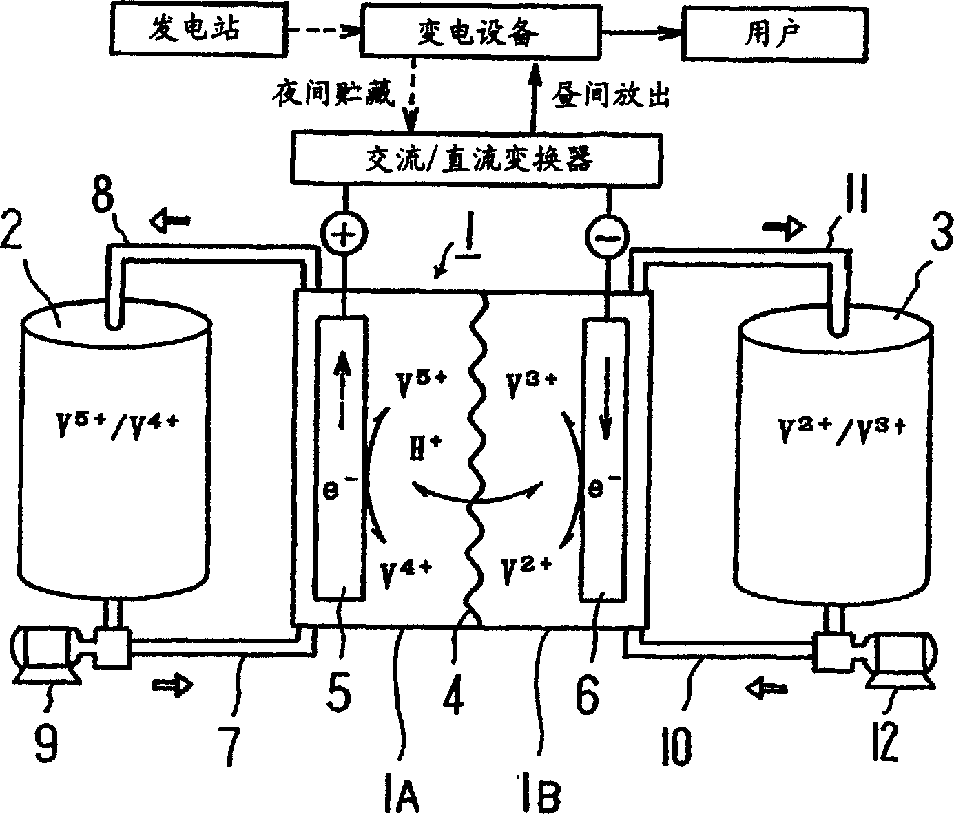
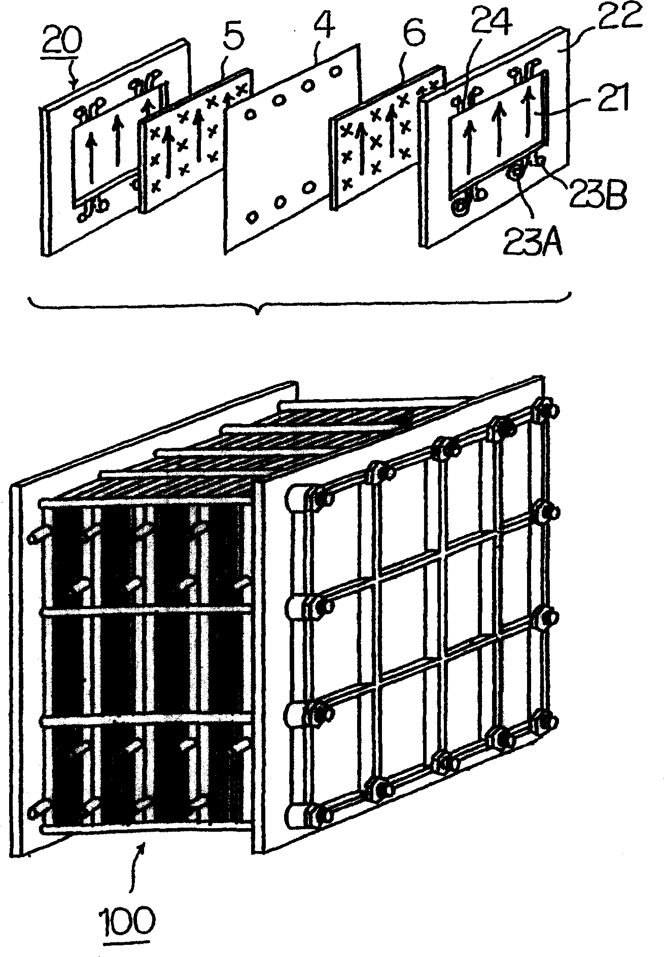
[0034] Use a 50kW-class battery pack to produce a capacity of 1 hour (electrolyte volume: plus and minus 1.5m each) 3 ) and 8-hour capacity (electrolyte volume: positive and negative 12m 3 )system. First, follow the figure 1 Explain how a redox flow battery works, then, follow figure 2 Describes the structure of the pool group.

[0035] This battery has a cell 1 partitioned into a positive electrode cell 1A and a negative electrode cell 1B using a separator 4 composed of an ion exchange membrane. A positive electrode 5 and a negative electrode 6 are placed in each positive electrode cell 1A and negative electrode cell 1B, respectively. In the positive electrode cell 1A, the positive electrode tank 2 for supplying and discharging the positive electrode electrolytic solution is connected through conduits 7 and 8 . In the negative electrode cell 1B, the negative electrode tank 3 that introduces and discharges the negative electrode electrolyte solution is connected through ...

Embodiment 2

[0044] A 50kW class battery pack was used to make a 1-hour capacity system, and the following three electrolytes were used for the test. Electrolyte volume, each positive and negative 1.5m 3 . Impurity amount, NH 4 is 18ppm. Samples with Si concentrations of 100, 50, and 40 ppm were used. For the adjustment of the impurity concentration, a polypropylene pleated filter manufactured by American Philta Co., Ltd. was used.

[0045] The main components of the electrolyte used here are: vanadium ion concentration 2.0 mol / liter, free sulfuric acid concentration 2.0 mol / liter, added phosphoric acid concentration 0.14 mol / liter. Cell resistance at various Si concentrations (Ω·cm 2 ) changes are shown in Figure 4 . The charging and discharging conditions are the same as in Example 1.

[0046] As a result, it was confirmed that when the Si concentration was greater than 40 ppm, the cell resistance increased, the capacity decreased, and the function as a battery was lost before 1...

Embodiment 3

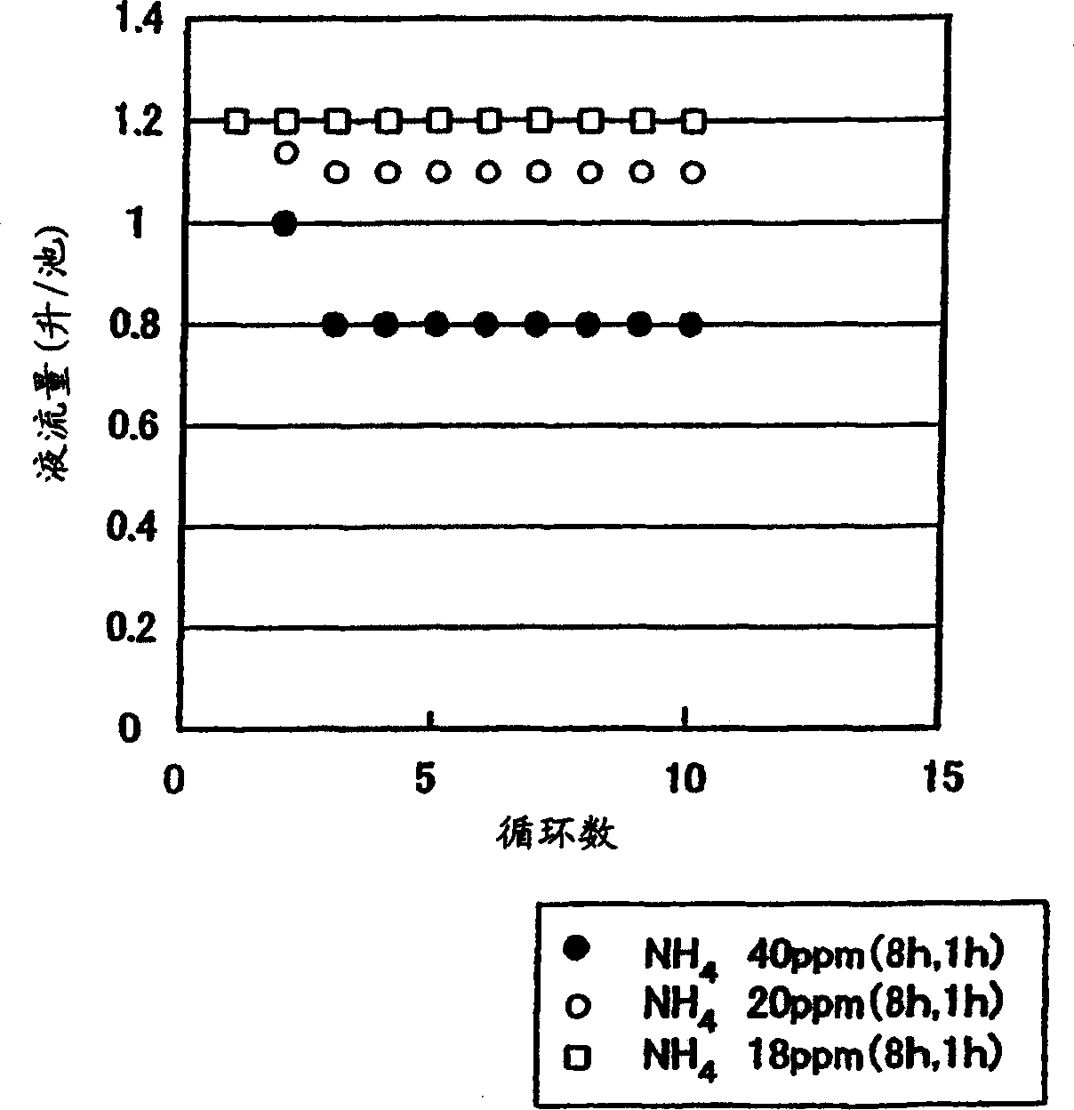
[0048] 50kW level pool group is used to make an 8-hour capacity (plus and minus 12m 3 ) system to investigate the relationship between the number of operating cycles and cell resistance. The main components of the electrolyte used here are: vanadium ion concentration 1.7 mol / liter, free sulfuric acid concentration 2.6 mol / liter, added phosphoric acid concentration 0.12 mol / liter. Additionally, making NH 4 Samples with a concentration of 20ppm and a Si concentration of 4, 10, and 40ppm. Cell resistance at various Si concentrations (Ω·cm 2 ) changes are shown in Figure 5 . The charging and discharging conditions are the same as in Example 1.

[0049] From shown in Figure 5 The results show that the cell resistance increases for samples with a Si concentration of 40ppm, but hardly changes for samples below 10ppm.


PUM


Abstract

The present invention provides electrolyte that can suppress reduction of battery efficiencies and capacities with increased cycles of charge / discharge of the battery, a method for producing the same, and a redox flow battery using the same electrolyte. The redox flow battery uses the electrolyte having a NH4 content of not more than 20 ppm and a relation of Si concentration (ppm)xelectrolyte quantity (m<3>) / electrode area (m<2>) of less than 5 ppm.m<3> / m<2>. By limiting a quantity of contaminants in the electrolyte, a clogging of carbon electrodes to cause reduction of the battery performances with increased charge / discharge operations can be suppressed.

Description

technical field [0001] The invention relates to an electrolytic solution for a vanadium redox flow battery, a manufacturing method thereof, and a redox flow battery using the electrolytic solution. Background technique [0002] Concerning the electrolytic solution of the vanadium-based redox flow battery, if it contains impurities such as Si compounds mixed in the manufacturing process, it will adversely affect the separator. Japanese Patent Application Laid-Open No. 8-148177 (Patent No. 3085634) indicates that these impurities can be removed by the following method to avoid their adverse effects. [0003] Under neutral or alkaline conditions, after completely dissolving ammonium metavanadate, make it acidic, precipitate polyvanadium compound, and use the obtained polyvanadium as electrolyte raw material. [0004] The Si compound is mixed in the process of obtaining the above-mentioned polyvanadium, but by suppressing the concentration of the Si compound to 1000 ppm, prefer...

Claims


Application Information

Patent Timeline
Patent Type & Authority Applications(China)
IPC IPC(8): H01M8/18C01G31/00H01M8/02H01M8/04H01M8/20H01M10/02
CPCY02E60/528H01M2300/0011H01M8/188H01M2300/0008Y02E60/50Y02P70/50
Inventor 久畑满中石博之德田信幸
Owner SUMITOMO ELECTRIC IND LTD
Why Eureka
Try Eureka