Optical filter

A technology of optical filter and optical fiber, applied in the field of optical filter

Inactive Publication Date: 2004-07-28
OKI ELECTRIC IND CO LTD
View PDF2 Cites 8 Cited by
  • Summary
  • Abstract
  • Description
  • Claims
  • Application Information

AI Technical Summary

Problems solved by technology

Traditional encapsulation methods cannot be

Method used


Image

  • Optical filter
  • Optical filter
  • Optical filter

Examples


Embodiment Construction

[0073] The various embodiments of the present invention are described below with reference to the accompanying illustrative drawings. In different embodiments, similar parts will be indicated by the same reference numerals, and no repeated description will be made.

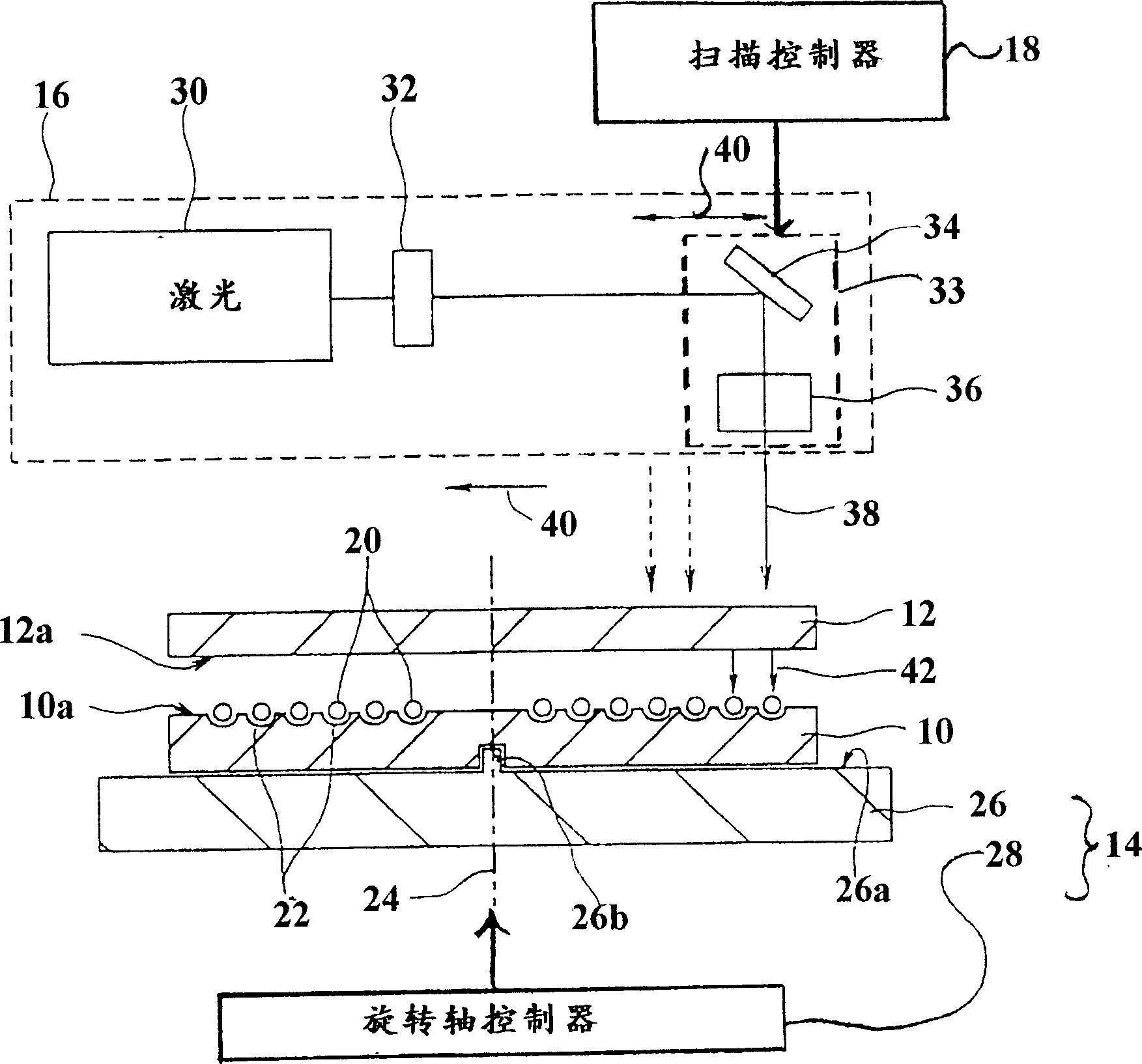
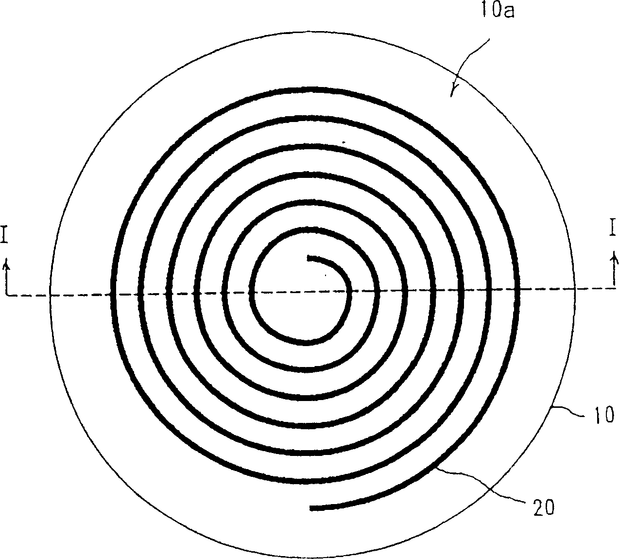
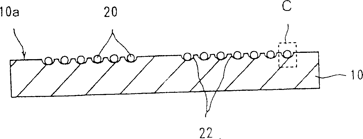
[0074] figure 1 The first embodiment of the apparatus for manufacturing an optical filter of the present invention is shown. The main components are a fiber holder 10, a phase mask 12, a rotating table 14, an optical system 16 and a scanning controller 18. The photosensitive optical fiber 20 is placed in the spiral groove 22 on the upper surface 10 a of the fiber holder 10. The fiber holder 10 is placed on the rotating table 14, and the phase mask 12 is fixed above the fiber holder 10. The optical system 16 emits a beam of ultraviolet light to illuminate the photosensitive optical fiber 20 through the phase mask 12. The scanning controller 18 controls the optical system 16 so that the ultraviolet light beam scans th...


PUM


Abstract

An optical filter comprises a fiber holder (10) having plane surface, on which a spiral groove (22) is; and a optical fiber (20) fixed in said spiral groove (22) and having refractive index modulated periodically.

Description

[0001] This application is a divisional application of the invention patent application 98115691.6 entitled "Methods and equipment for manufacturing optical filters, optical filters, fiber holders and phase masks" on July 7, 1998. Technical field [0002] The present invention relates to an optical filter composed of a Bragg grating formed inside an optical fiber, a method and apparatus for manufacturing such an optical filter, and a fiber holder and a phase mask used in the manufacturing method. ). Background technique [0003] Intra-fiber Bragg grating, also referred to as fiber Bragg grating or FBG for short, can be used as an optical filter in the field of optical communication to achieve the purpose of wavelength division multiplexing and dispersion compensation. U.S. Patent No. 5367588 describes a method of manufacturing Bragg gratings in fibers. This method uses ultraviolet light to illuminate a photosensitive fiber through a phase grating cover. The phase grating cover is ...

Claims


Application Information

Patent Timeline
IPC IPC(8): G02B6/124G02B6/34G02B27/42G03F7/00H01L31/18
CPCY02P70/50
Inventor 寺尾芳孝野本勉西木玲彦
Owner OKI ELECTRIC IND CO LTD
Why Eureka
Try Eureka