Waste gas treatment system for paint drying oven

A waste gas treatment and drying furnace technology, applied in the direction of incinerators, combustion methods, combustion types, etc., can solve the problems of increasing furnace temperature, increasing energy consumption, and not treating waste gas

Inactive Publication Date: 2004-08-04
HEFEI BRANCH CORP JIANGXI CHANGHE VEHICLE
View PDF0 Cites 16 Cited by
  • Summary
  • Abstract
  • Description
  • Claims
  • Application Information

AI Technical Summary

Problems solved by technology

For this reason, the method of extracting waste gas and then incinerating it has been tried to convert the organic matter into high-temperature oxide gas after high-temperature combustion, and discharge the organic matter harmlessly. However, the existing exhaust gas treatment device of the primer drying furnace is to set a square oil fume outlet in the middle of the furnace body, and heat and burn the extracted oil fume. The disadvantages are:
[0003] 1. The position and shape of the range fume outlet are unreasonable, the exhaust gas extraction is not thorough, and a large amount of exhaust gas still leaks out
[0004] 2. The exhaust fume outlet is located in the middle of the drying furnace, which is the highest temperature section of the drying furnace. If the exhaust air volume is increased, the drying temperature in the furnace will be affected. If the furnace temperature is increased, the energy consumption will be increased.
[0005] 3. The exhaust gas is not treated after incineration, and the high temperature of the exhaust gas cannot be effectively recycled.

Method used


Image

  • Waste gas treatment system for paint drying oven
  • Waste gas treatment system for paint drying oven
  • Waste gas treatment system for paint drying oven

Examples


Embodiment

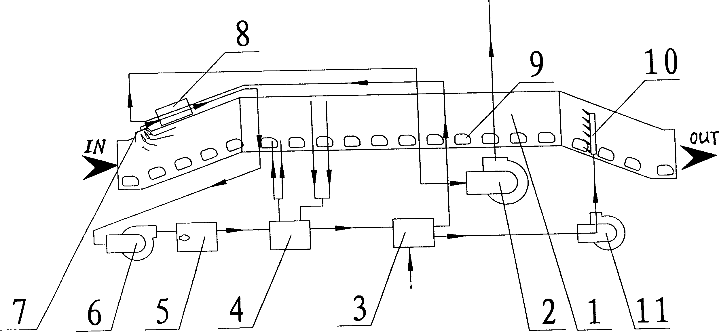
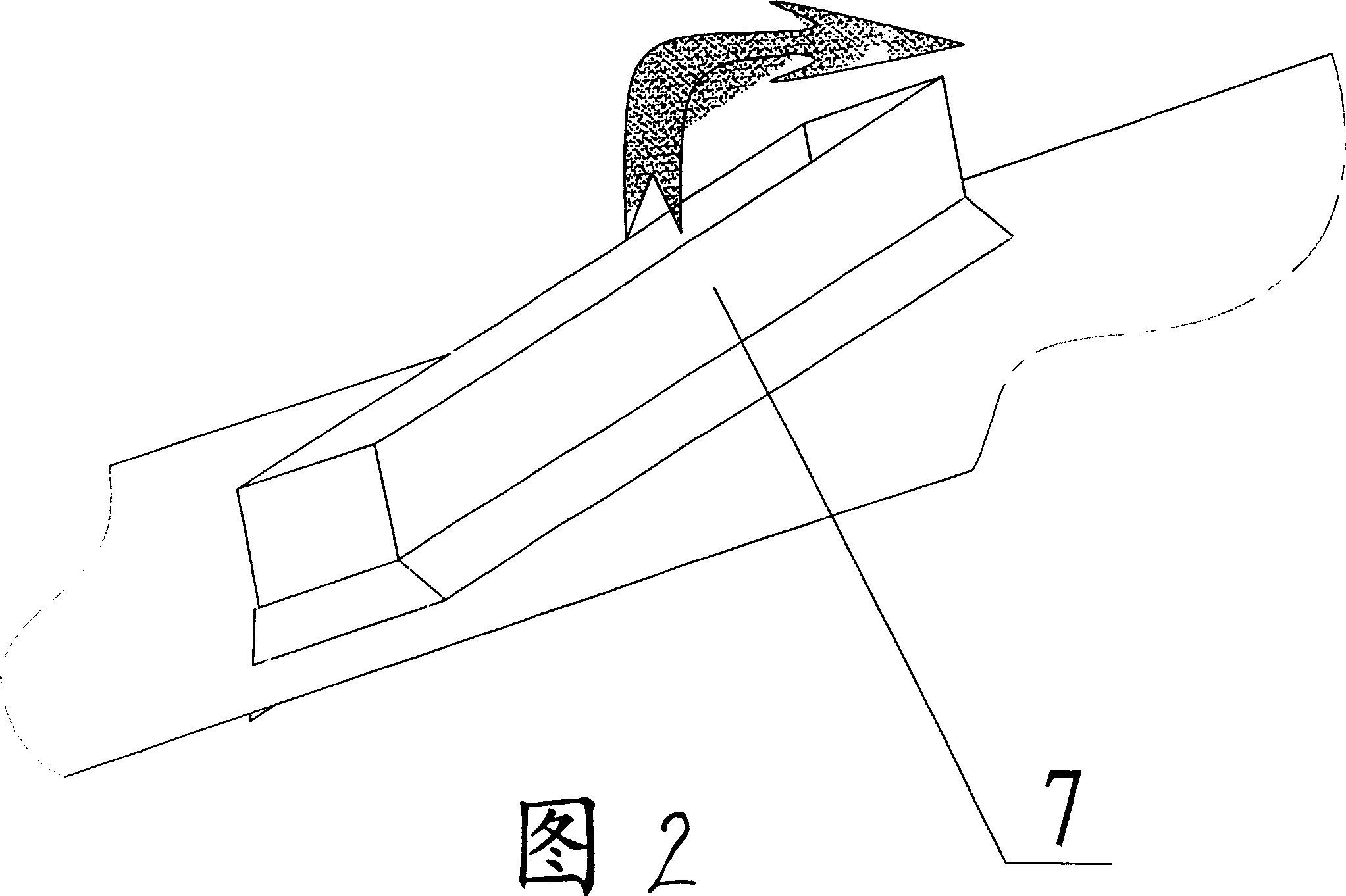
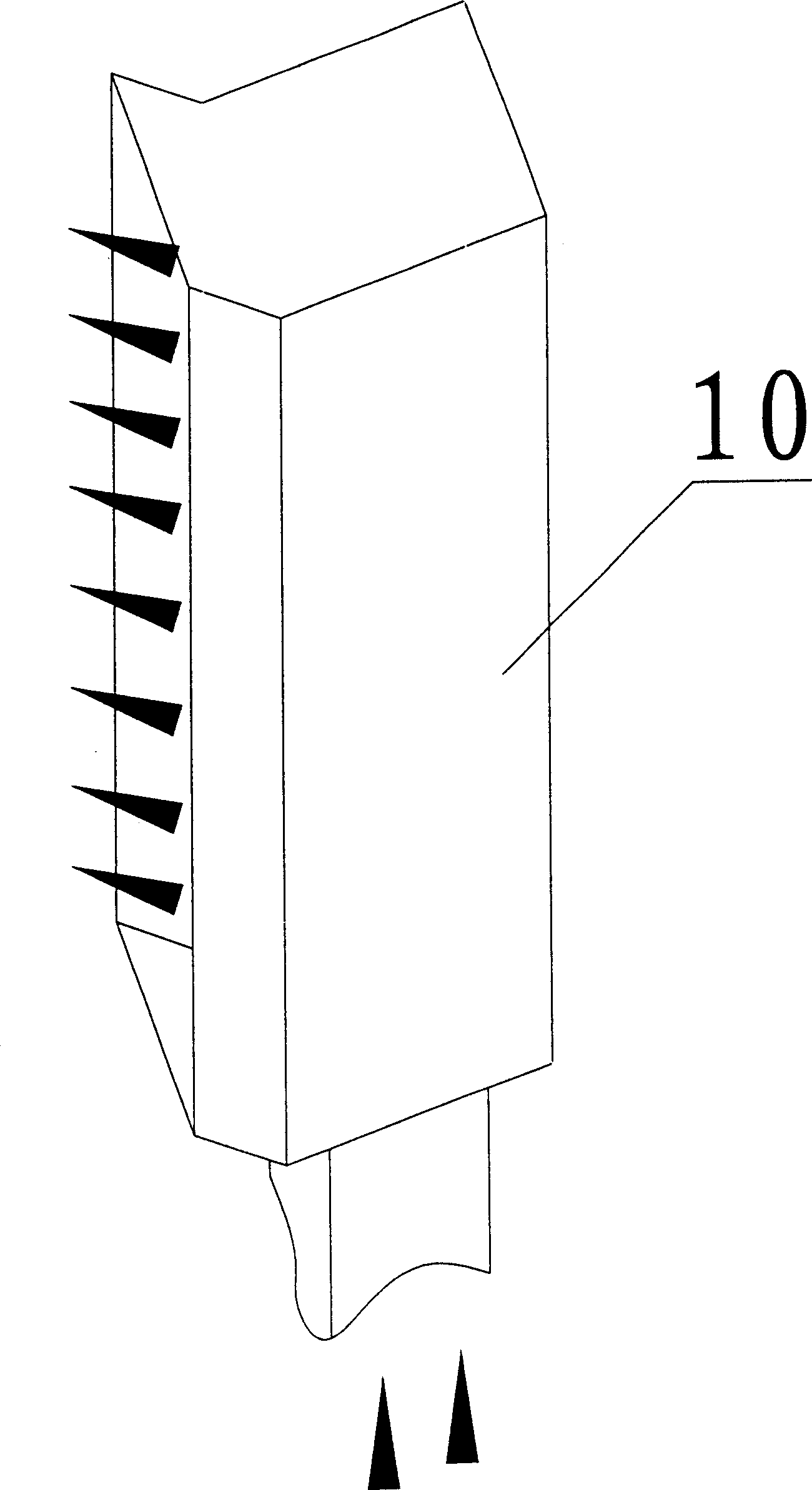
[0027] In this embodiment, fresh air first passes through the air-flue gas heat exchanger 3 and enters the air outlet 10 at the product outlet OUT through the heat machine 11, and the air runs along the inner channel of the drying furnace 1 to the exhaust hood at the product inlet IN. 7. The exhaust gas then enters the exhaust gas-flue gas heat exchanger 8 and then enters the incinerator 5 through the exhaust gas exhaust fan 6. After being incinerated at high temperature, the exhaust gas becomes flue gas and enters the air in multiple furnaces—the flue gas of the flue gas heat exchanger 4 Enter the exhaust gas-flue gas heat exchanger 8 flue gas pipes on the top of the drying furnace shell again, and then turn back to the high-pressure exhauster 2 to empty. 0~15 meters of the product outlet OUT end are provided with an air supply port 10, and the air supply port 10 is a tubular body with several oblique openings that enters the air from the bottom and blows out from the side to ...


PUM


Abstract

A waste gas treating system for paint oven with product entrance and exis is composed of said paint oven, incinerator, air exhaustor, and multi-stage heat exchanger. The air comes in the oven via product entrance and then becomes waste gas, which is exhausted into incinerator for burning it. The high-temp fume flows through multi-stage heat exchanger and then is discharged.

Description

technical field [0001] The invention relates to the field of environmental protection waste gas treatment, in particular to a paint drying furnace waste gas treatment system. Background technique [0002] For the general conveyor chain drying furnace, especially the organic waste gas produced by the primer drying furnace, it is difficult to effectively collect and treat the organic waste gas generated by the general paint drying furnace during the product baking process. The product inlet and outlet of the drying furnace diffuse outwards, causing air pollution in the external environment. The painted products are transported along the furnace body of the drying furnace from the product inlet through the conveyor chain, and are heated and dried in the drying furnace. The paint on the surface is volatilized and decomposed during the heating process. A large amount of soot and exhaust gas is generated, which gradually rises to the top of the heating furnace. Since the soot and...

Claims


Application Information

Patent Timeline
Patent Type & Authority Applications(China)
IPC IPC(8): F23G7/08
Inventor 马自成
Owner HEFEI BRANCH CORP JIANGXI CHANGHE VEHICLE
Why Eureka
Try Eureka