
Component for light isolator, its mfg. method and light isolator using such component for light isolator

A technology of optical isolator and manufacturing method, applied in optical components, optics, instruments, etc., can solve the problems of deterioration of optical characteristics, increase of thermal stress, deterioration of extinction ratio, etc.

Inactive Publication Date: 2004-08-11
KYOCERA CORP
View PDF2 Cites 3 Cited by
  • Summary
  • Abstract
  • Description
  • Claims
  • Application Information

AI Technical Summary

Problems solved by technology

Furthermore, the gas emitted from the organic adhesive 19 adheres to the surface of optical components such as laser chips or lenses, and there is a risk of deteriorating optical properties.
[0016] In addition, in the optical isolator element 20 in which the plate-shaped polarizers 17 and 18 are bonded on both sides of the Faraday rotator 16 with low-melting-point glass 19, the glass transition temperature of the low-melting-point glass 19 is as high as several hundred degrees. Therefore, after melting and fixing each member, thermal stress increases when cooling to room temperature, and there is a risk of cracks occurring in each member or the low-melting glass 19
In addition, if thermal stress is applied to the Faraday rotator 16, the extinction ratio of the light passing through the Faraday rotator 16 deteriorates, and various characteristics of the optical isolator 15, especially the reverse direction attenuation characteristics deteriorate.

Method used


Image

  • Component for light isolator, its mfg. method and light isolator using such component for light isolator
  • Component for light isolator, its mfg. method and light isolator using such component for light isolator
  • Component for light isolator, its mfg. method and light isolator using such component for light isolator

Examples


Embodiment Construction

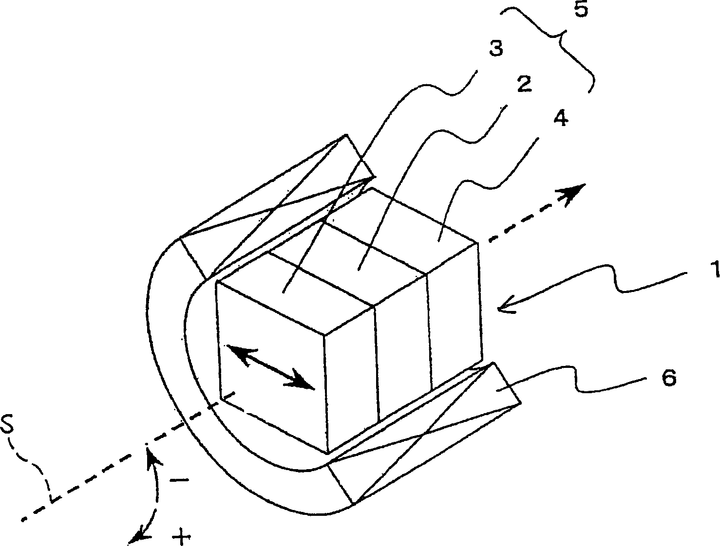
[0044] figure 1 It is a perspective view showing a main part of an optical isolator related to an embodiment of the present invention by cutting away. In this figure, an optical isolator 1 includes an optical isolator element 5 that is integrated by laminating flat polarizers 3 and 4 on both sides of a flat Faraday Rotator (Faraday Rotator) 2. And the cylindrical magnet body 6 which accommodates the element 5 for optical isolators. In addition, as will be described later, the optical isolator element 5 is manufactured by bonding a similarly large polarizer substrate to both sides of a large Faraday rotator substrate, and then subdividing it into appropriate sizes.

[0045] The Faraday rotator 2 is made of, for example, a bismuth-substituted garnet crystal or the like, and its thickness is set so that the polarization plane of incident light having a predetermined wavelength is rotated by 45 degrees. In general, in order to rotate the plane of polarization, it is necessary t...


PUM

PropertyMeasurementUnit
roughnessaaaaaaaaaa
surface smoothnessaaaaaaaaaa
particle diameteraaaaaaaaaa

Abstract

An optical isolator (1) is constructed such that an optical isolator element (5) in which at least one flat Faraday rotator (2) and at least two flat polarizers (3,4) are bonded to each other into an integral unit by van der Waals forces or hydrogen-bonding forces acting between bonding surfaces of the Faraday rotator (2) and the polarizers (3,4) is accommodated in a tubular magnetic element (6).

Description

technical field [0001] The present invention relates to an optical isolator element used to remove return light generated when light emitted from a light source is introduced into various optical elements or optical fibers, a manufacturing method thereof, and an optical isolator using the optical isolator element. Background technique [0002] In an optical communication module, etc., light emitted from a light source such as a laser light source is incident on various optical elements or optical fibers, but a part of the incident light is reflected or scattered on the end surface or inside of various optical elements or optical fibers. . Part of the reflected or scattered light is returned to the light source as return light as it is. Therefore, an optical isolator is used to prevent the return light from returning to the light source. [0003] Conventionally, such an optical isolator is constructed by disposing a flat-plate Faraday rotator between two polarizers, and acc...

Claims


Application Information

Patent Timeline
Patent Type & Authority Applications(China)
IPC IPC(8): C03C27/04C03C27/06G02F1/09
CPCC03C27/06C03C27/04Y10S372/703G02F1/093
Inventor 庄田学史佐藤恭史古坚由纪子重冈义之
Owner KYOCERA CORP
Features
  • Generate Ideas
  • Intellectual Property
  • Life Sciences
  • Materials
  • Tech Scout
  • Unparalleled Data Quality
  • Higher Quality Content
  • 60% Fewer Hallucinations
Learn More