Thermal developing appts. and thermal developing method and program

A thermal development, computer program technology, used in photography, optics, instruments, etc., can solve problems such as abnormal temperature, spread diagnosis, and inability to obtain density grayscale.

Inactive Publication Date: 2004-08-11
KONICA MINOLTA INC
View PDF0 Cites 0 Cited by
  • Summary
  • Abstract
  • Description
  • Claims
  • Application Information

AI Technical Summary

Problems solved by technology

In addition, when heaters are overlapped to avoid heater gaps, temperature abnormalities are likely to occur on the drum surface corresponding to the overlapped portion.
Based on the measured value of the abnormal density part, a calibration LUT is formed to offset it. Using this calibration LUT, when printing a diagnostic image later, an appropriate density gradation cannot be obtained, causing adverse effects on diagnosis.

Method used


Image

  • Thermal developing appts. and thermal developing method and program
  • Thermal developing appts. and thermal developing method and program
  • Thermal developing appts. and thermal developing method and program

Examples


no. 1 Embodiment approach

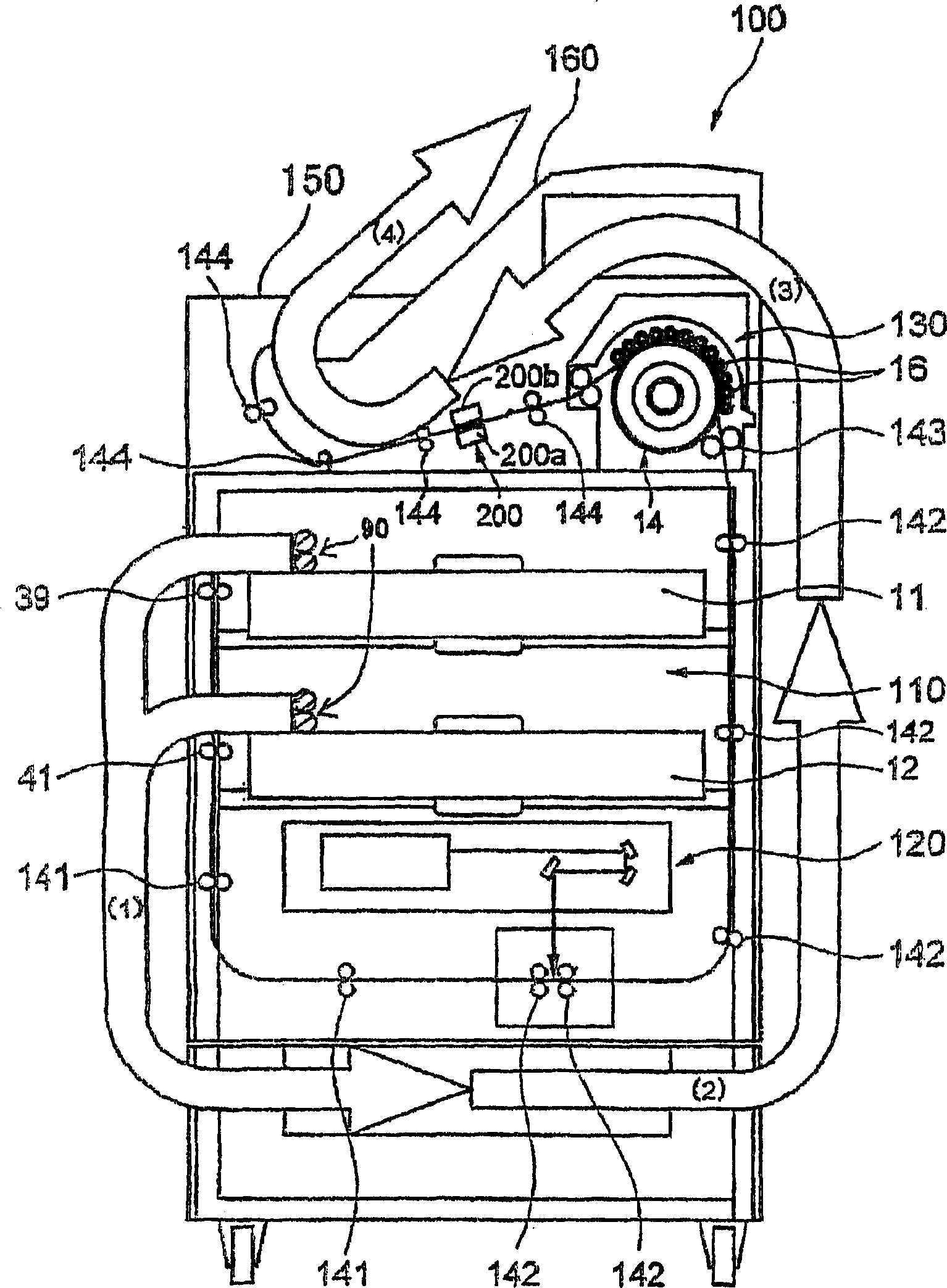
[0092] Figure 8 It is a block diagram illustrating the function of the first embodiment of the thermal developing device for implementing the thermal developing method of the present invention. Figure 8 The flow chart of the processing of the thermal developing device shown.

[0093] Such as Figure 8 As shown, the thermal development device of the present invention is provided with: an exposure member 120 for performing an exposure step, a thermal development member 130 for performing a thermal development step, a measurement member 200 for performing a measurement step, and a calibration step The calibration component 350 is the control component 400 for implementing the control step, and the counting component 500 is used for the counting step.

[0094] As shown in FIG. 9, in the exposure unit 120, exposure is performed based on the calibration image data (also referred to as calibration image), and the exposed image is developed and visualized in the thermal development uni...

no. 2 Embodiment approach

[0107] Picture 12 Is a functional block diagram illustrating the second embodiment of the thermal developing device for implementing the thermal developing method of the present invention, Figure 13 Is to illustrate based on Picture 12 The flow chart of the processing of the thermal developing device shown.

[0108] Such as Picture 12 As shown, the thermal development device of the present invention is provided with: an exposure member 120 for performing an exposure step, a thermal development member 130 for performing a thermal development step, a measurement member 200 for performing a measurement step, and a calibration step The calibration component 350 is the control component 400 used to implement the control step, and the temperature detection component 600 used to implement the temperature detection step.


PUM


Abstract

An image processing apparatus, comprising: an exposing device for exposing an image forming material so as to form a latent image on the image forming material based on image data; a thermal developing device for developing and visualizing the latent image on the exposed image forming material so as to form an image; a measuring device for measuring the image density of the image on the developed image forming material; a calibrating device for forming a table to define a relation between an image signal and image density on the basis of plural different test image data and measured-image densities thereof; a counting device for counting the number of the image forming material developed within predetermined time; and a controlling device for controlling the exposing device, the thermal developing device, the measuring device, the calibrating device and the counting device; wherein the controlling device stop forming the table for predetermined time when the counting device counts the number of the developed image forming material more than predetermined number.

Description

Technical field [0001] The present invention relates to a thermal development device, a thermal development method and a program, and in detail relates to a thermal development device, a thermal development method and a program capable of processing the film with an appropriate density when forming a medical diagnostic image on the film. Background technique [0002] Since medical laser imagers express diagnostic images in shades, there is a strong hope for the basic function of stabilizing the output density for a long time. In addition, when photographing / printing the front, side, and lumbar spine of the chest, it is characterized by many ways of use: For one patient, take several pictures such as front, side, lateral flexion, and lateral back flexion, up to 4 consecutive pictures. photography. [0003] In such a medical laser imager, in order to make the digital / video signal (designated density signal) from each modality form a certain density on the film, there is a so-called...

Claims


Application Information

Patent Timeline
Patent Type & Authority Applications(China)
IPC IPC(8): G03D13/00H04N1/00H04N1/12H04N1/191
CPCH04N1/00978H04N1/00986H04N1/12H04N1/1911H04N1/00832G03D13/002
Inventor 下地雅也
Owner KONICA MINOLTA INC
Why Eureka
Try Eureka