Device for treating powder particles by rotary flow

A processing device, powder and granular technology, applied in the direction of mixer with rotating stirring device, powder suspension method granulation, raw material granulation method, etc., can solve the problem of fine powder and granular flying, uncontrollable formation good etc.

A processing device, powder and granular technology, applied in the direction of mixer with rotating stirring device, powder suspension method granulation, raw material granulation method, etc., can solve the problem of fine powder and granular flying, uncontrollable formation good etc.

CN1522173AInactive Publication Date: 2004-08-18NARA MACHINERY

Image

  • Device for treating powder particles by rotary flow
  • Device for treating powder particles by rotary flow
  • Device for treating powder particles by rotary flow

Examples


Embodiment Construction

[0034] The present invention will be described in detail based on a flow processing device for powder and granular bodies in a preferred embodiment.

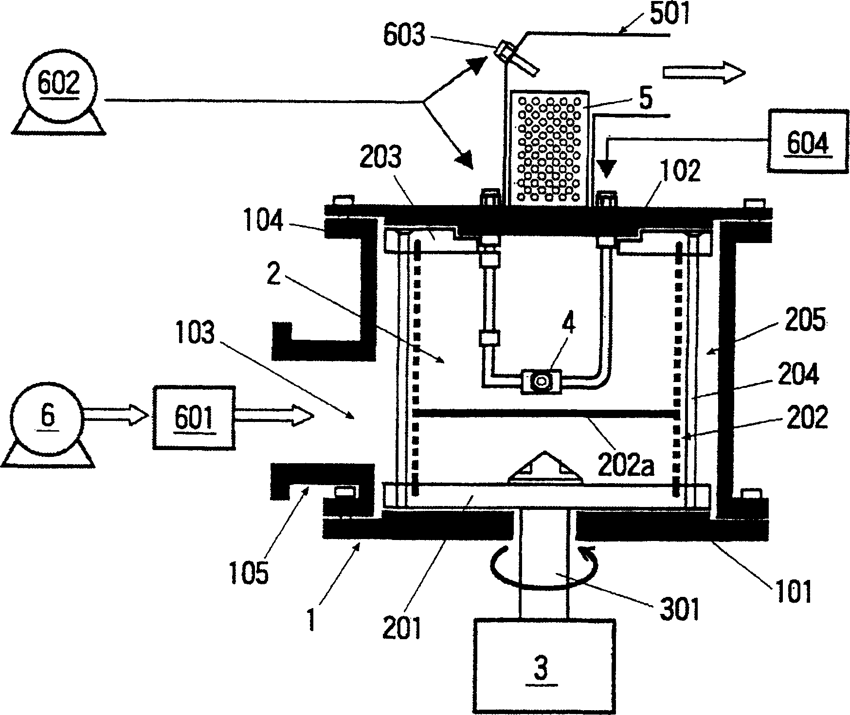
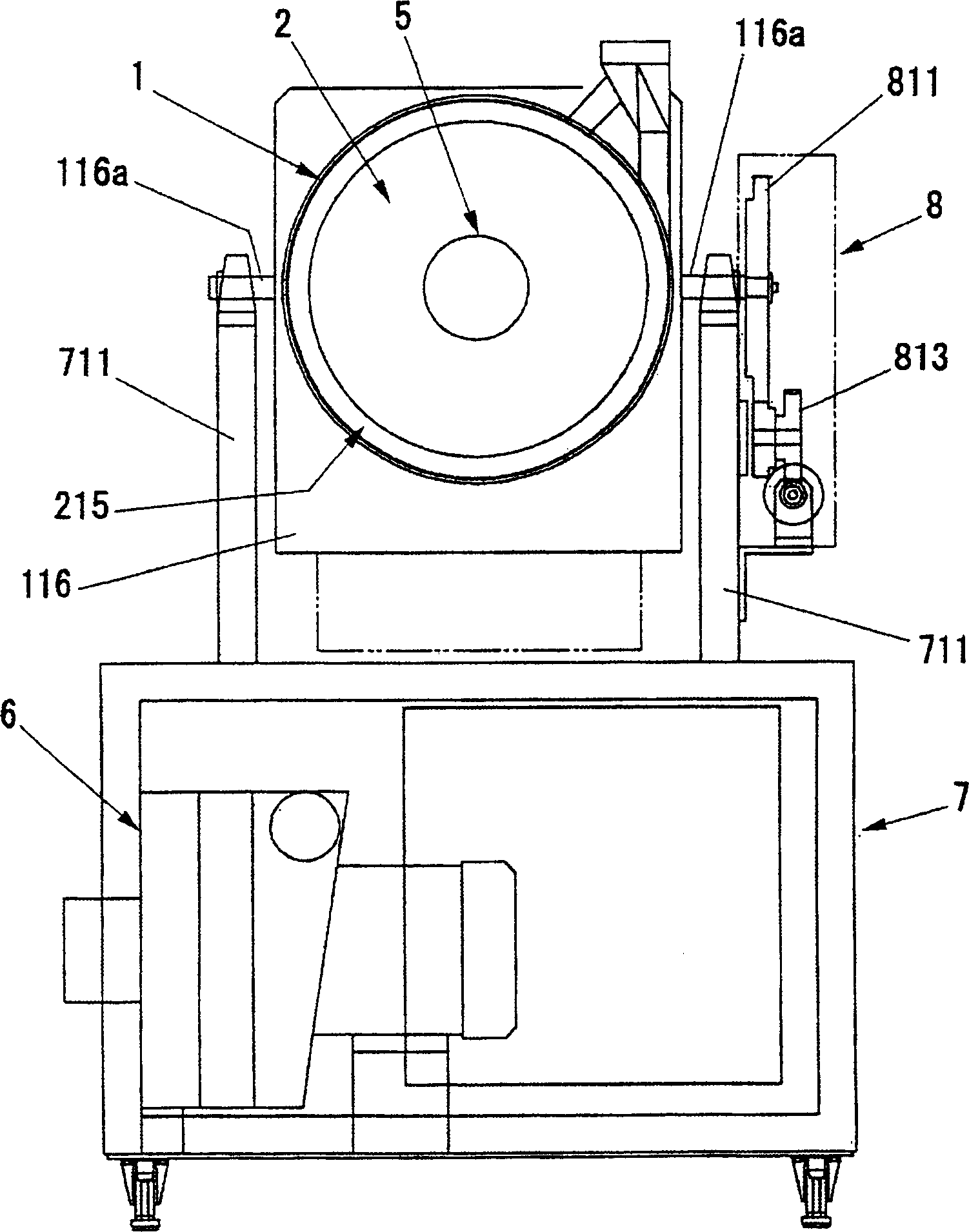
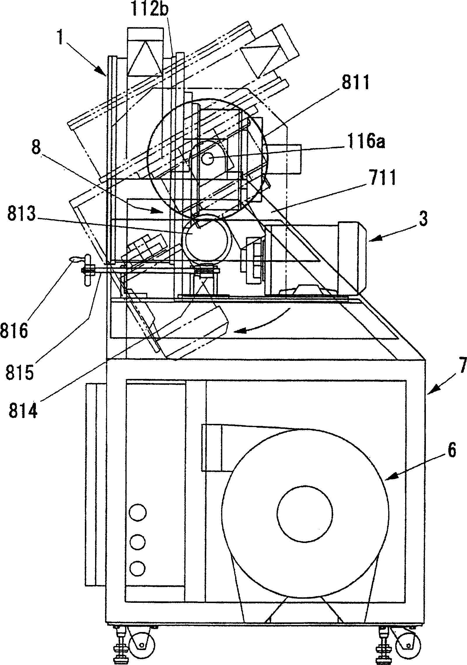
[0035] refer to figure 1 and the same as the second embodiment Figure 11 A first embodiment in which the device is configured vertically will be described. Reference numeral 1 is a cylindrical casing, and a cylindrical processing chamber 2 for processing powdery or granular materials is arranged in the casing 1 with a certain space apart from the inner wall surface of the casing 1 .

[0036] In the processing chamber 2 , the lower fixing plate 201 is rotatably and interlockingly connected to the driving device 3 via the rotating shaft 301 . The peripheral panel 202 provided on the outer peripheral surface of the processing chamber 2 constitutes a predetermined ventilation device for allowing predetermined gases such as various gases and air to flow into the processing chamber 2, and forms a structure that can ventilate from ...


PUM


Abstract

The present invention relates to a rotating fluidized bed apparatus for powder particle. A gas circulation path is formed at the periphery of the treatment chamber 2 via the circumferential faceplate 202, 212, and the circumferential faceplate is adapted to rotate around an axis. Behavior of powder particles can be controlled by introducing gas from the periphery of the treatment chamber via the circumferential plate 212 to exert centripetal force on the powder particle, while exerting centrifugal force on the powder particles accompanying rotation of the circumferential plate 212. In another aspect, by making the arrangement proportion of the bag filter 5 inside the treatment chamber 2 wider than the surface width of the dispersion plate 212 or larger than the surface area of the dispersion plate 212, it is possible to cause gas that has flowed into the treatment chamber 2 to be discharged at a lower rate at an axial region inside the treatment chamber 2 where centrifugal force is weak and discharge rate is fast. It is possible to carry out optimal operation control of introduction and discharge of gas for fluidized bed behavior.

Description

technical field [0001] The present invention relates to a flow processing device for processing powder and granular body through mixing, granulation, coating, surface modification, drying, reaction, etc., especially relates to a flow processing device suitable for processing granular powder and granular body. Background technique [0002] Generally speaking, as a device that flows various gases or air into the processing chamber to mix, granulate, coat, dry or react powder or grain, there are known Figure 20 The fluidized bed device shown. [0003] This fluidized bed apparatus constitutes a frustoconical container 2A in which a distribution plate for ventilation (for example, a punched perforated plate) 3A is disposed on the bottom surface. When the device is used for powder drying, heated air flows into the container 2A from below the dispersion plate 3A to suspend and flow the powder 1A put into the container 2A, and at the same time perform drying. [0004] And when thi...

Claims


Application Information

Patent Timeline
18 Aug 2004
Publication
CN1522173A
IPC
B01F27/96; B01F33/40; B01J2/16; B01J8/38
CPC
B01F13/02; B01F2003/1264; B01F9/00; B01J2/16; B01J8/38; B01F13/0255; B01F7/32; B01F23/566
Inventors
若松喜浩; 绵野哲