Perforating device

A technology of hole position and hole processing, which is applied in the direction of boring/drilling, drilling/drilling equipment, electrical components, etc. It can solve the problems of longer opening time and longer punch stroke, so as to improve quality and Yield rate, the effect of avoiding edge collapse

Inactive Publication Date: 2004-09-08
SEIKO PRECISION CO LTD
View PDF1 Cites 9 Cited by
  • Summary
  • Abstract
  • Description
  • Claims
  • Application Information

AI Technical Summary

Problems solved by technology

However, when the hole is drilled from this position, the distance from the punch to the die, that is, th...

Method used


Image

  • Perforating device
  • Perforating device
  • Perforating device

Examples


Embodiment Construction

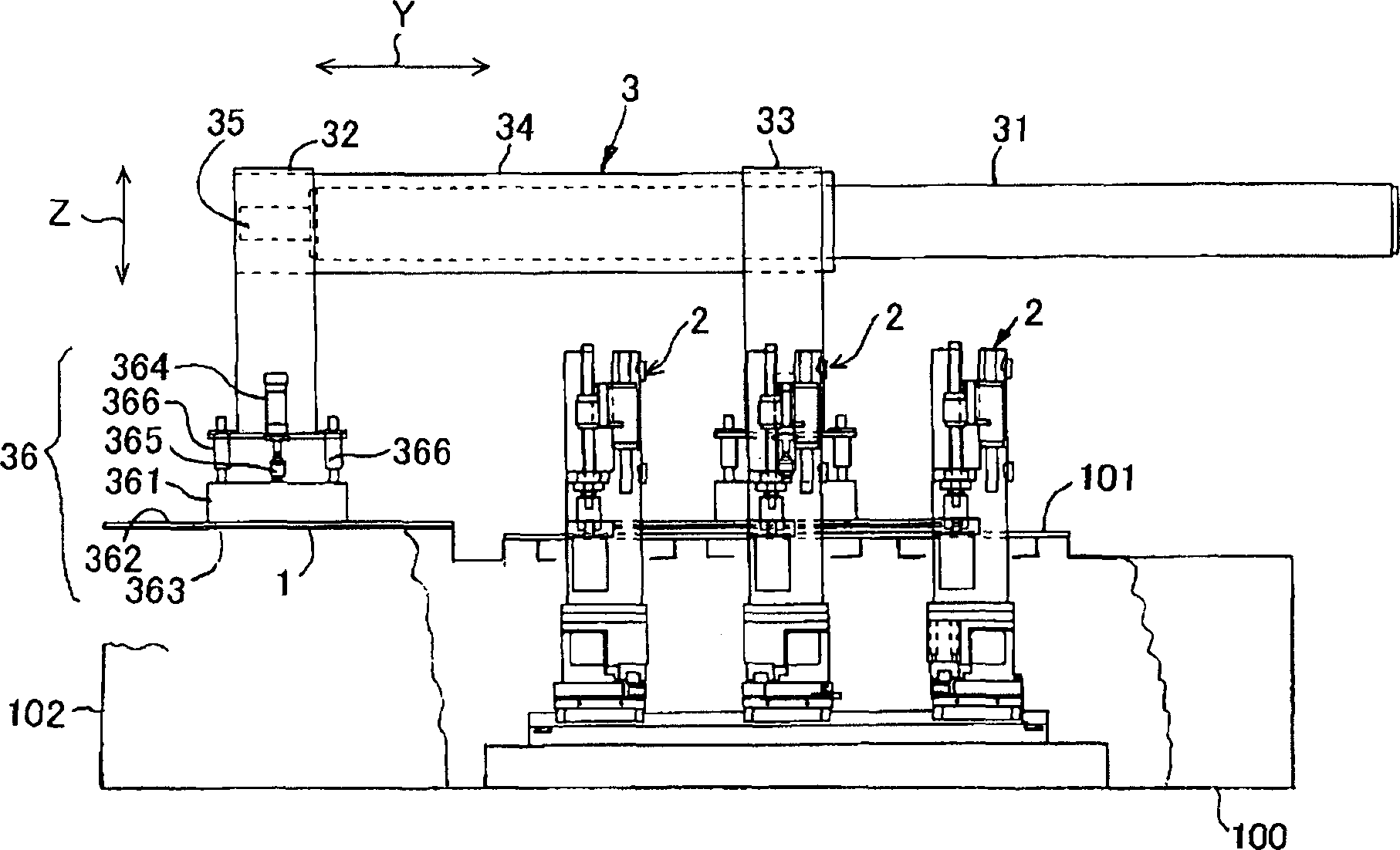
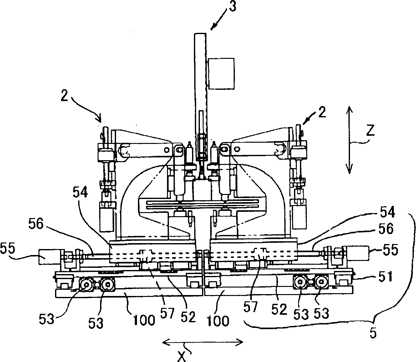
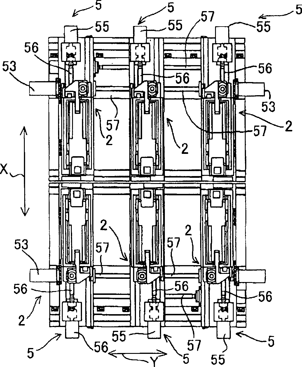
[0024] Below, refer to Figure 1 to Figure 11 The structure of the drilling device of the present invention will be described. First, a general description of the overall structure is given. In this hole opening device, there are six hole opening mechanisms 2 for opening holes on the plate-shaped workpiece 1, and the input mechanism 3 that holds the plate-shaped workpiece and transports it to the hole-opening mechanism is respectively connected with the hole-opening mechanism. An integrated camera mechanism 4 and a moving mechanism 5 capable of moving each opening mechanism independently of each other. And, the opening device has such as Figure 10 The shown image processing mechanism 6 processes the shooting results of the camera mechanism 4, the computing mechanism 7 that calculates the processing results of the image processing mechanism, and controls the driving of the camera mechanism 4 and the input mechanism 3, according to the calculation results of the computing mec...


PUM


Abstract

A punch 22 is driven by a servo-motor 231 and a feed screw 232 or the like rotated and driven by the servo-motor. A stand-by position of the punch 22 before boring and a driving speed are made variable by a control of the servo-motor 231. Thereby, a movement stroke of the punch 22 is made minimum and a boring processing time can be shortened. It can be avoided that irregularity, burr, crack or peeling off is generated on the processing hole by an appropriate driving speed of the punch.

Description

technical field [0001] The invention relates to a hole-drilling device for a plate-shaped workpiece, in particular to a hole-drilling device for a printed circuit board. Background technique [0002] In electronic devices and the like, multilayer printed wiring boards in which a plurality of substrates on which circuit patterns are formed are stacked and fixed are widely used. However, when the substrates are laminated, if the positions of the circuit patterns are shifted from each other, the predetermined functions and performances of the printed wiring board cannot be fully exhibited. For this reason, at least two guide holes should be provided on the prescribed positions of each substrate, and the guide shaft of the jig should be inserted into the guide holes to realize the positioning of each substrate. [0003] In the prior art, when the guide hole is opened, the circuit board is inserted between the die and the punch opposite to the die, and driven by a hydraulic cyli...

Claims


Application Information

Patent Timeline
IPC IPC(8): B26F1/14B23B41/00B26F1/00B26F1/02B26F1/04H05K3/00
CPCB26F1/02B26F1/04B26F1/14B26F2210/08H05K3/005
Inventor 外村裕司
Owner SEIKO PRECISION CO LTD
Why Eureka
Try Eureka