Coiling apparatus of yarn

A yarn winding machine and yarn technology, applied in spinning machines, textiles and papermaking, and conveying filamentous materials, etc., can solve problems such as irregular winding bobbins, achieve simple structure, reduce area, The effect of reducing the number

Inactive Publication Date: 2004-09-22
MURATA MASCH LTD
View PDF3 Cites 14 Cited by
  • Summary
  • Abstract
  • Description
  • Claims
  • Application Information

AI Technical Summary

Problems solved by technology

As a result, irregular winding packages can occur and steps can be formed on

Method used


Image

  • Coiling apparatus of yarn
  • Coiling apparatus of yarn
  • Coiling apparatus of yarn

Examples


no. 1 example

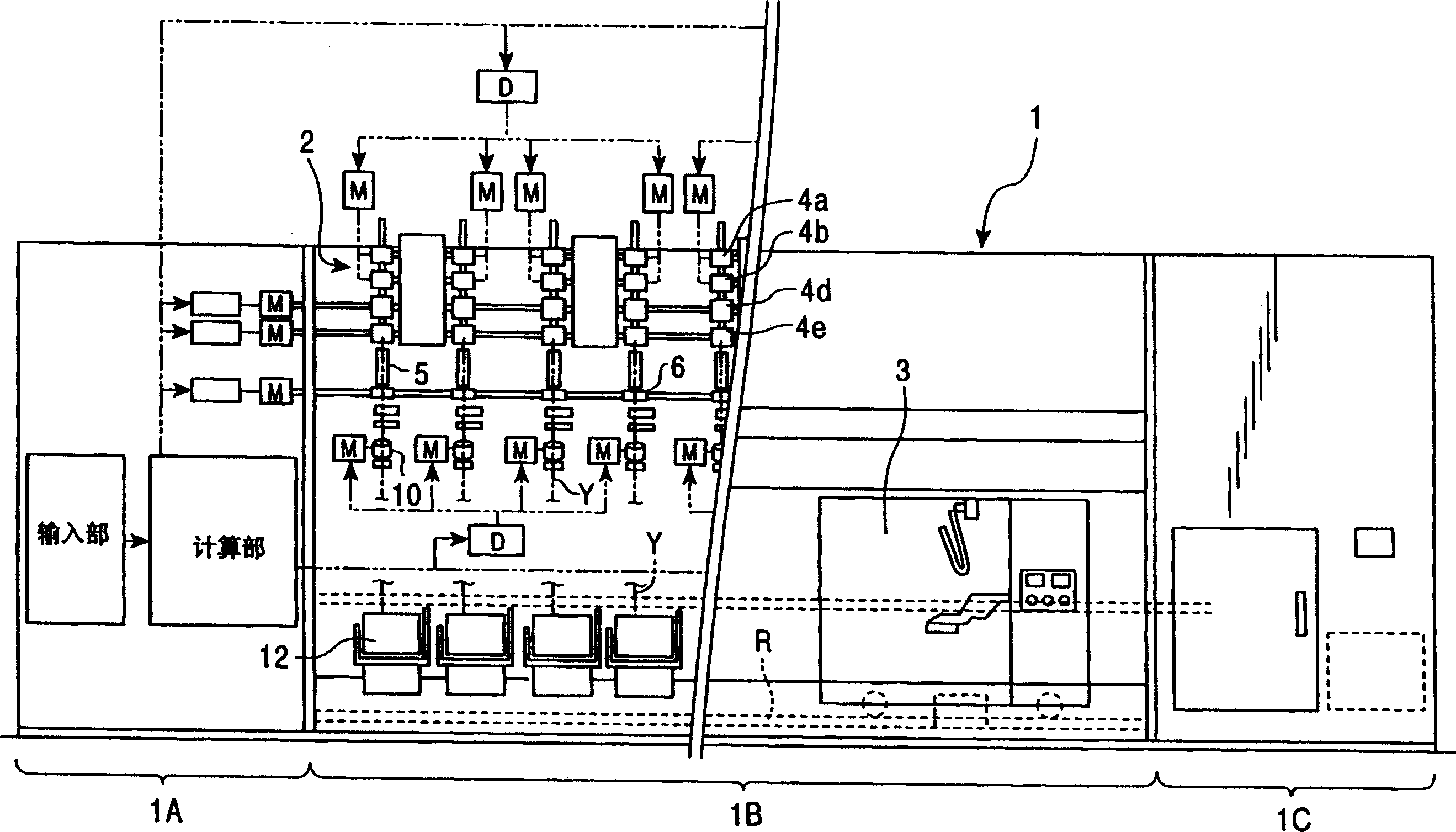
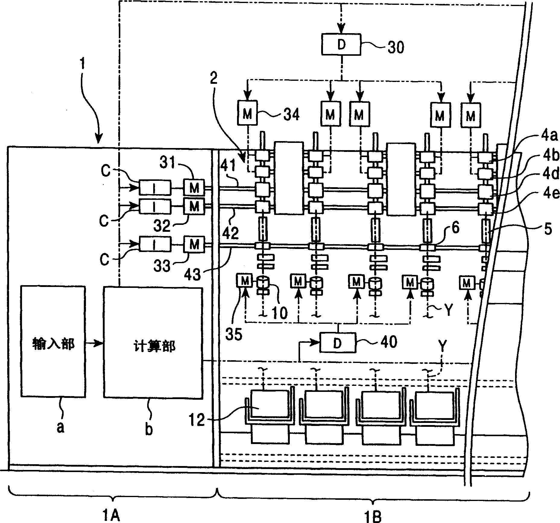
[0055] figure 1 It is a front view of an example of the spinning machine 1 to which the present invention is applied. figure 2 is a schematic enlarged view of a part of the internal structure of the spinning machine 1. The spinning machine is constituted by, for example, an air spinning machine. The main components of the spinning machine 1 include: a control section 1A; a spinning section 1B, in which a large number of spinning units 2 are arranged side by side; a blower section 1C; and a work trolley 3, which includes a yarn Splicing device, and can run freely between the spinning units 2 along the track R.

[0056] The control section 1A of the spinning machine 1 implements the following control: controlling the operation of the drive motors 31, 32, 33 of the drive shafts 41, 42, 43 for supplying all spinning units 2 constituting the spinning section 1B. Applying driving force; controlling the operation of the motors 34, 35 provided for each spinning unit 2; controlling t...

no. 2 example

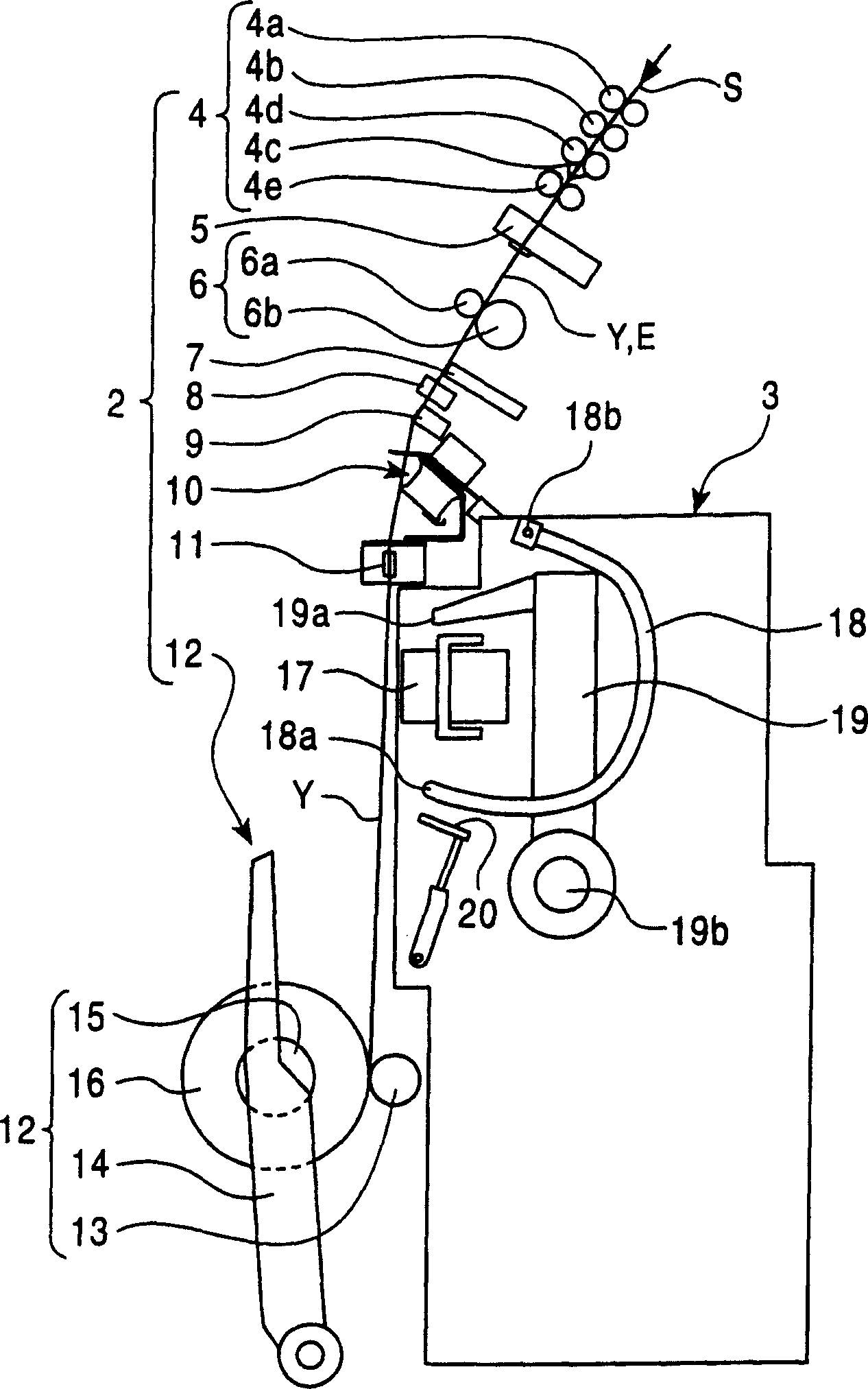
[0104] In the yarn slack eliminating device 10 according to the present invention, the upstream side guide 23 of the slack eliminating roller 21 may be fixed, and the downstream side guide 36 may be movable, such as Figure 20 shown. However, considering the aforementioned configuration in which the upstream-side guide 23 is closer to the yarn defect detector 9 than the downstream-side guide 36, if it is necessary to satisfy that the yarn Y is removed from the yarn defect detector 9 before the slack eliminating operation is to be performed, 9 Excluding this condition, it is preferable to advance the upstream side guide 23 to bend the yarn Y when the yarn Y is removed from the yarn defect detector 9. This reduces the movement stroke and prevents parts from protruding excessively compared to the case where the downstream side guide 36 advances and retreats.

[0105] However, in addition to operating the yarn defect detector 9 as described above, for example, a controller for el...

no. 3 example

[0107] In the previously described embodiments, the yarn slack eliminating device is used to eliminate possible slack in the yarn splicing operation. However, the yarn slack eliminating device can also be used to constitute a spinning machine capable of properly adjusting the winding speed to slack the yarn Y even in normal spinning operation so that the yarn Y is always It is wound around the slack removing roller 21 . An example is a spinning machine in which the yarn Y is always wound on the slack eliminating roller 21 when forming a cone yarn to absorb the yarn that may be wound on the large diameter side and the small diameter side of the cone yarn due to the difference in winding speed. The resulting winding tension difference.

[0108] When forming a cone yarn, the yarn tension tends to vary because the yarn winding radius in the axial direction changes even within one traverse stroke. Therefore, the yarn slack eliminating device according to the invention is arranged...


PUM


Abstract

The present invention stabilizes a yarn tension in a yarn winder in which a plurality of winding units are disposed, each of the winging units being provided with a yarn slack eliminating device. A transmitted force adjusting mechanism is provided to adjust a rotative driving force transmitted by a slack eliminating roller of a yarn slack eliminating device to an unwinding tension applying member. The transmitted force adjusting mechanism can be set so that when a load acting on the unwinding tension applying member increases above a predetermined value, the unwinding tension applying member rotates or rotatively moves independently of the slack eliminating roller. When winding tension is weak, the unwinding tension applying member rotates integrally with the slack eliminating roller to tense a yarn. When the winding tension exceeds a predetermined value, the unwinding tension applying member prevents the winding tension from becoming excessive to suppress a variation in tension. When the transmitted force adjusting mechanism is configured so as to vary the force transmitted to the unwinding tension applying member, it is easy to deal with spinning conditions.

Description

technical field [0001] The present invention relates to a yarn winding machine having a yarn slack eliminating device for eliminating yarn slack provided between a yarn supply side and a winding device; in particular, the present invention relates to such a A yarn winding machine, which employs a yarn slack eliminating device for winding up slack yarn that may occur during a yarn splicing operation, for example, to adjust when restarting the winding operation after the yarn splicing operation yarn tension, and suppresses changes in winding tension during normal winding. Background technique [0002] In a spinning machine such as an air spinning machine, a spun yarn is produced using a sliver (fiber bundle) as a raw material, and the spun yarn is wound into a predetermined package; if a yarn defect is detected, Then the defective part of the yarn will be cut and removed by the cutter. Then, the yarn splicing device splices the front end of the yarn subsequently supplied fro...

Claims


Application Information

Patent Timeline
IPC IPC(8): B65H51/22B65H59/18B65H69/00D01H13/10
CPCB65H2701/31B65H59/18B65H69/00B65H51/22D01H13/104D01H13/10
Inventor 平尾修重山昌澄八木宏幸泽田晴稔
Owner MURATA MASCH LTD
Why Eureka
Try Eureka