Optical pickup-use object lens, optical pickup and optical disk unit

A technology of optical disc device and pick-up, which is applied in the direction of beam guiding device, optics, optical elements, etc., can solve the problems of focusing diffraction limit, difficult laser, etc., and achieve the effect of reducing the number of parts

Inactive Publication Date: 2004-09-22
SONY CORP
View PDF0 Cites 0 Cited by
  • Summary
  • Abstract
  • Description
  • Claims
  • Application Information

AI Technical Summary

Problems solved by technology

The objective lens 201 of monolithic structure with glass molding that has the aspherical surface 201a that is used in the prior art is difficult to focus the laser light to the diffraction limit due to the above-mentioned chromatic aberration.

Method used


Image

  • Optical pickup-use object lens, optical pickup and optical disk unit
  • Optical pickup-use object lens, optical pickup and optical disk unit
  • Optical pickup-use object lens, optical pickup and optical disk unit

Examples


Embodiment 2

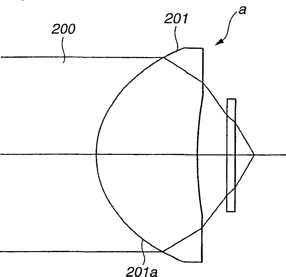
[0184] The objective lens 15 of embodiment 2 has the 1st lens group GR1 that is made up of the 1st lens L1 and the 2nd lens group GR2 that is made up of the 2nd lens L2, and this 1st lens L1, by having the refractive surface S 2r is the base plane and forms the diffraction plane S 2d and the composite surface S 2 The second lens L2 is a single-piece aspheric glass molded lens with large magnification. A protective layer 30 made of polycarbonate is disposed between the second lens L2 and the image surface (recording layer of the optical disc 100).

[0185] The numerical values ​​of the constituent lenses of Example 2 are listed in Table 3 below.

[0186] r i

d i

Nitrogen

r 1 =∞

d 1 =1.00

resin

r 2 =7.650

d 2 =0.20

r 3 =1.337

d 3 =1.60

LAH53

r 4 =6.486

d 4 =0.74

r 5 =∞

d 5 =0.1

polycarbonate

Image plane = ∞

[0187] Embodiment 2, because the 1st lens L1 is f...

Embodiment 3

[0193] The objective lens 15 of embodiment 3 has the 1st lens group GR1 made up of the 1st lens L1 and the 2nd lens group GR2 made up of the 2nd lens L2, and this 1st lens L1, by having the refraction surface S 2r A synthetic resin layer 18 is laminated as a base surface, and a diffraction surface S is formed on the surface of the synthetic resin layer 18. 2d Composite surface S 2 The second lens L2 is a single piece of aspheric glass molded lens with large magnification. A protective layer 30 made of polycarbonate is disposed between the second lens L2 and the image surface (recording layer of the optical disc 100).

[0194] The numerical values ​​of the constituent lenses of Example 3 are listed in Table 5 below.

[0195] r i

d i

Nitrogen

r 1 =∞

d 1 =1.00

SBSL7

r 2r =7.750

d 2 =0.01

r 2d =7.750

d 3 =0.20

resin

r 3 =1.337

d 4 =1.60

LAH53

r 4 =6.486

d 5 =0.74

r 5 =∞ ...

Embodiment 5

[0212] The objective lens 15 of Example 5 has a first lens group GR1 composed of a first lens L1 having a refracting surface S with a second surface S, and a second lens group GR2 composed of a second lens L2. 2r is the basal plane and forms the diffractive surface S 2d while the composite surface S 2 The second lens L2 is a single-piece aspherical glass molded lens with large magnification. Between the second lens L2 and the image plane (the recording layer of the optical disc 100 ), the protective layer 30 made of polycarbonate is arranged.

[0213] The numerical value of each constituent lens of Example 5 is shown in the following Table 9.

[0214] r i

d i

Nitrogen

r 1 =∞

d 1 =1.00

resin

r 2 =7.650

d 2 =3.00

r 3 =1.337

d 3 =1.60

LAH53

r 4 =6.486

d 4 =0.74

r 5 =∞

d 5 =0.1

polycarbonate

Image plane = ∞

[0215] In the objective lens 15 of the fifth embodiment, ...


PUM

PropertyMeasurementUnit
thicknessaaaaaaaaaa
thicknessaaaaaaaaaa

Abstract

The present invention is relative to an objective lens (15) for an optical pickup, having a numerical aperture not less than 0.8, and adapted for correcting the chromatic aberration at an image point on an optical axis for light with a wavelength within several nm about a reference wavelength which is not larger than 420 nm. This objective lens is made up by a first lens set GR1, having a compound surface S2 of a refractive surface S2r and a diffractive surface S2d, and a second lens set GR2, having a positive refractive power, looking from the light source side. The compound surface of the first lens set is formed by adding the diffractive surface having the positive refractive power to the refractive surface which is an aspherical surface having the negative refractive power. The lens forming the second lens set is a single lens including at least one aspherical lens. This objective lens is small-sized, permits effective correction of chromatic aberration and enables the laser light to be converged to close to the diffraction threshold.

Description

technical field [0001] The present invention relates to an objective lens used in an optical pickup device for recording information by irradiating an optical recording medium with a beam of laser light or the like and reproducing the information recorded on the optical recording medium, and an optical pickup using the objective lens The present invention relates to an optical disc device, more specifically, an objective lens capable of focusing a light beam on a recording surface of an optical recording medium to the diffraction limit, an optical pickup device using the objective lens, and an optical disc device. Background technique [0002] As the information recording medium, a non-contact optical recording medium with a high recording density is currently used. In the optical recording medium, information can be recorded by irradiating a recording surface with a light beam, for example, laser light, and the recorded information can be reproduced. Such an optical record...

Claims


Application Information

Patent Timeline
Patent Type & Authority Applications(China)
IPC IPC(8): G02B9/04G02B27/00G11B7/135G11B7/22
CPCG11B7/1374G11B2007/13727G02B27/4238G11B7/1392G02B27/0037G02B9/04G11B7/22G11B7/1353G02B13/18
Inventor 高桥丰和日根野哲
Owner SONY CORP
Why Eureka
Try Eureka