Back light module and liquid crystal display device

A liquid crystal display and backlight module technology, which is applied in the directions of instruments, optics, nonlinear optics, etc., can solve problems such as cost burden, unevenness, and restrictions on the miniaturization of liquid crystal displays, and achieve simplification of the production process, cost reduction, and thinning of the volume Effect

Inactive Publication Date: 2004-09-29
AU OPTRONICS CORP
View PDF0 Cites 6 Cited by
  • Summary
  • Abstract
  • Description
  • Claims
  • Application Information

AI Technical Summary

Problems solved by technology

[0010] However, since the production of color filter films is cumbersome and the price is not cheap, the overall price of liquid crystal displays cannot be further reduced.
In addition, because the configuration of the color filter film and black matrix on the substrate often has unevenness, the color filter must be covered with a flat layer on the color filter film and black matrix ( over coating) to achieve the purpose of surface flattening, which will increase the complexity of color filter production and is also a burden in terms of cost
In addition, since most of the current liquid crystal displays use color filter substrates and thin film transistor matrix substrates to sandwich the liquid crystal layer, this design structure will limit the development of miniaturization of liquid crystal displays

Method used


Image

  • Back light module and liquid crystal display device
  • Back light module and liquid crystal display device
  • Back light module and liquid crystal display device

Examples


Embodiment Construction

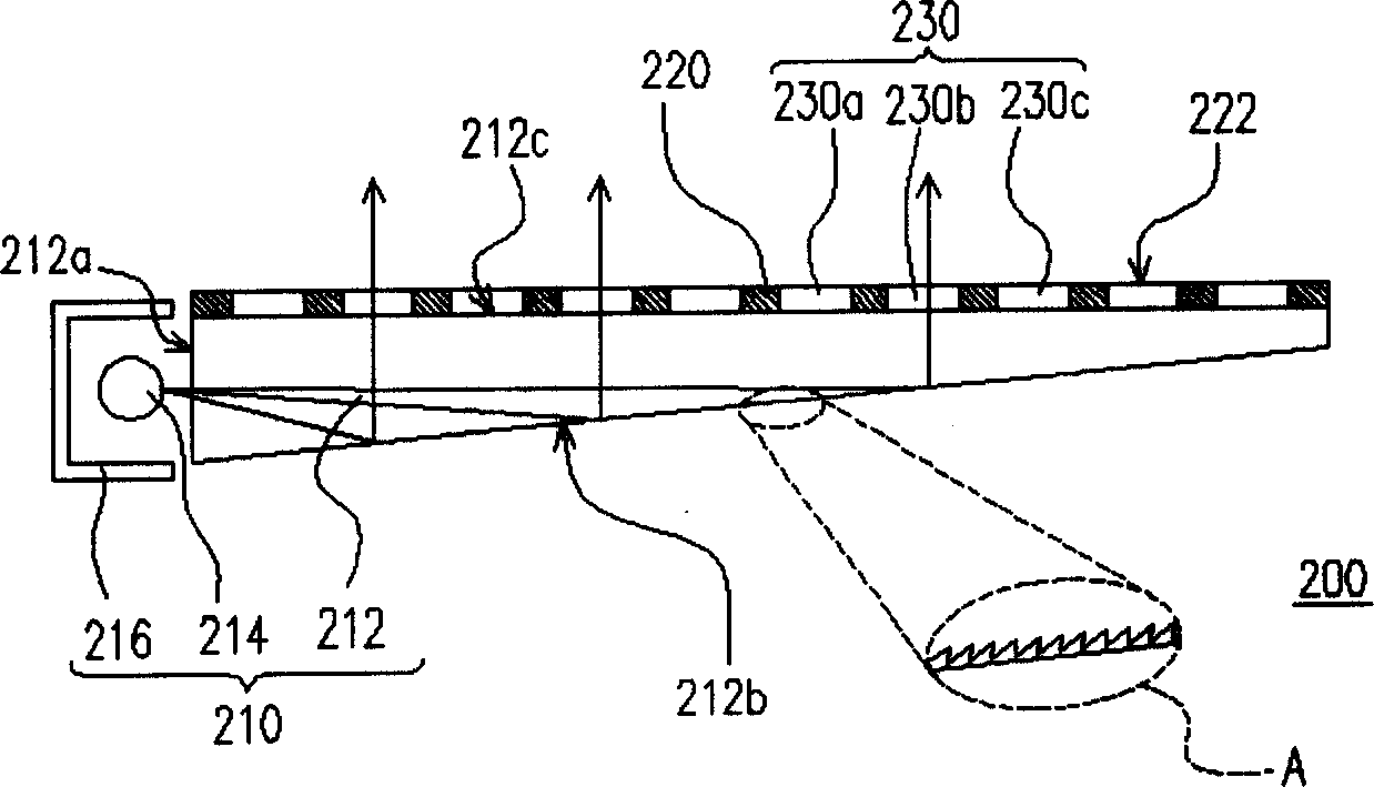
[0060] figure 2 It is a structural schematic diagram of a backlight module in a preferred embodiment of the present invention. The backlight module 200 is composed of a surface light source 210 , a light-shielding matrix 220 and a fluorescent layer 230 . Wherein, the surface light source 210 is composed of a light guide plate 212 , a line light source 214 and a reflector 216 . The light guide plate 212 can be a wedge-shaped light guide plate, which has a light incident surface 212a, a light diffusion surface 212b and a light exit surface 212c, and the light diffusion surface 212b has a plurality of V-shaped notches (visible in the figure area A). The reflection cover 216 is disposed beside the light incident surface 212 a, and the line light source 214 is disposed inside the reflection cover 216 . The above-mentioned line light source 214 is, for example, a cold cathode fluorescent lamp (CCFL) suitable for providing white light or an LED array. The light provided by the li...


PUM


Abstract

The back light module is used to provide one color area light source and consists of mainly one area light source, one mask matrix and one fluorescent layer. The mask matrix is configured onto the surface of the area light source and has several lattices to expose the area light source, and the fluorescent layer is configured inside the lattices. The fluorescent layer makes the light the area light source generates become colored. In addition, the present invention proposes one kind of LCD comprising mainly the said back light module, one light polarizing film on the fluorescent layer, one electrode layer on the light polarizing film, one matrix base board over the back light module, and one liquid crystal layer between the matrix base board and the back light module.

Description

technical field [0001] The present invention relates to a backlight module (Back Light Module) and a liquid crystal display (Liquid Crystal Display, LCD), and in particular to a backlight module capable of providing a colored surface light source and a liquid crystal display using the backlight module. Background technique [0002] In order to match the mode of modern life, the volume of video or image devices tends to be thinner and lighter day by day. Although the traditional cathode ray display (CRT) still has its advantages, due to the structure of the internal electronic cavity, the display is bulky and takes up space, and there are still problems such as radiation damage to the eyes when displaying. Therefore, the flat panel display (Flat Panel Display), such as liquid crystal display (LCD), organic light-emitting display (OLED) or plasma display (Plasma Display Panel, PDP), developed in conjunction with optoelectronic technology and semiconductor manufacturing technol...

Claims


Application Information

Patent Timeline
Patent Type & Authority Applications(China)
IPC IPC(8): G02F1/13357H01J61/00
Inventor 谢宗勋张哲志
Owner AU OPTRONICS CORP
Why Eureka
Try Eureka