Method for working nut screw of ball screw

A ball screw and processing method technology, applied in metal processing, metal processing equipment, applications, etc., can solve the problems of increased nut processing costs and increased processing time, and achieve the effects of shortening processing time and improving processing accuracy

Inactive Publication Date: 2004-09-29
NSK LTD
View PDF0 Cites 9 Cited by
  • Summary
  • Abstract
  • Description
  • Claims
  • Application Information

AI Technical Summary

Problems solved by technology

This increases the machining time and thus the nut machining costs

Method used


Image

  • Method for working nut screw of ball screw
  • Method for working nut screw of ball screw
  • Method for working nut screw of ball screw

Examples


Embodiment Construction

[0029] Now, with reference to the accompanying drawings, the preferred processing methods for nuts for ball screws are given below

[0030] Description of Examples.

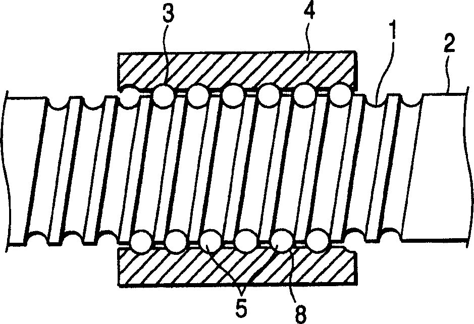
[0031] figure 1 is a longitudinal sectional side view of the ball screw according to the first embodiment of the present invention. The ball screw includes a screw shaft 2 and a nut 4, wherein the screw shaft 2 includes a helical groove 1, and the nut 4 includes a helical groove 3, and makes a plurality of balls 5 in the helical groove of the screw shaft 2 and the nut 4 Scroll between 1 and 3. Generally, the spiral groove 1 of the screw shaft 2 is formed by rolling working using a rolling die, or is formed by grinding so as to have a Gothic arch shape. On the other hand, the helical groove 3 of the nut 4 is machined with a lathe, or cut with a specially designed rotary tool, so as to have a gothic arched shape.

[0032]Subsequently, the blank of the nut 4 is heat-treated, for example by carburizing and quenc...


PUM


Abstract

A method for working a nut screw for a ball screw has a first step of lathing or cutting a spiral-shaped rolling surface of the nut screw for a ball screw on which balls of the ball screw are allowed to roll, a second step of heat treating, for example, carburizing and quenching or high-frequency quenching the spiral-shaped rolling surface obtained in the first step to thereby harden the top surface layer of the rolling surface and, a third step of surface finishing the hardened top surface layer of the spiral-shaped rolling surface obtained in the second step according to an electrolytic polishing.

Description

technical field [0001] The present invention relates to a method of machining a nut screw of a ball screw, including a deflector-type ball screw. Background technique [0002] Ball screw components that convert rotary motion to linear motion or linear motion to rotary motion can amplify small torques, thereby providing large thrust forces, and allow precise positioning in linear directions. Thanks to this performance, ball screws are widely used in machine tools, semiconductor-related equipment, and industrial robots. [0003] Such as Figure 4 As shown, the ball screw includes a screw shaft 102 and a nut 104, wherein the screw shaft 102 includes a helical groove 101, and the nut 104 includes a helical groove 103, and makes a plurality of balls 105 in the spiral of the screw shaft 102 and the nut 104. rolling in grooves 101 and 103. The spiral groove 101 of the screw shaft 102 is formed by rolling using a rolling die, or by grinding into a Gothic arch. On the other hand, ...

Claims


Application Information

Patent Timeline
Patent Type & Authority Applications(China)
IPC IPC(8): B23H5/08B23H9/00B23P15/00F16H25/22
CPCY10T29/49689F16H2025/2481B23H9/00B23H2200/10B23H5/08F16H25/2223F16H2025/2242Y10T74/19749B23P15/00Y10T29/49691B21H3/08
Inventor 神谷彻足立努岩泽隆二
Owner NSK LTD
Why Eureka
Try Eureka